

Active part of transformer
A transformer and device body technology, applied in the direction of transformer/inductor core, transformer/inductor coil/winding/connection, inductor/transformer/magnet manufacturing, etc., can solve the problem of large no-load loss and increased core hysteresis loss , no-load loss increase and other issues, to achieve the effect of no-load current will not increase, reduce stress, increase area
- Summary
- Abstract
- Description
- Claims
- Application Information
AI Technical Summary
Problems solved by technology
Method used
Image

Examples
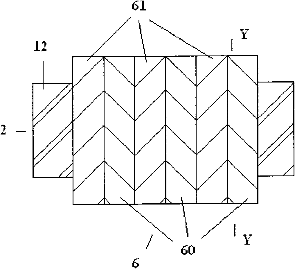
Embodiment 2
[0028] The second embodiment is the second transformer body in which the iron core column is placed horizontally. The structure of this embodiment, see image 3 and Figure 4 .
[0029] Except for the following differences, this embodiment is identical to Embodiment 1 in other parts. The cross sections of the second stem 2 , the third stem 3 and the fourth stem 4 are circular.
Embodiment 3
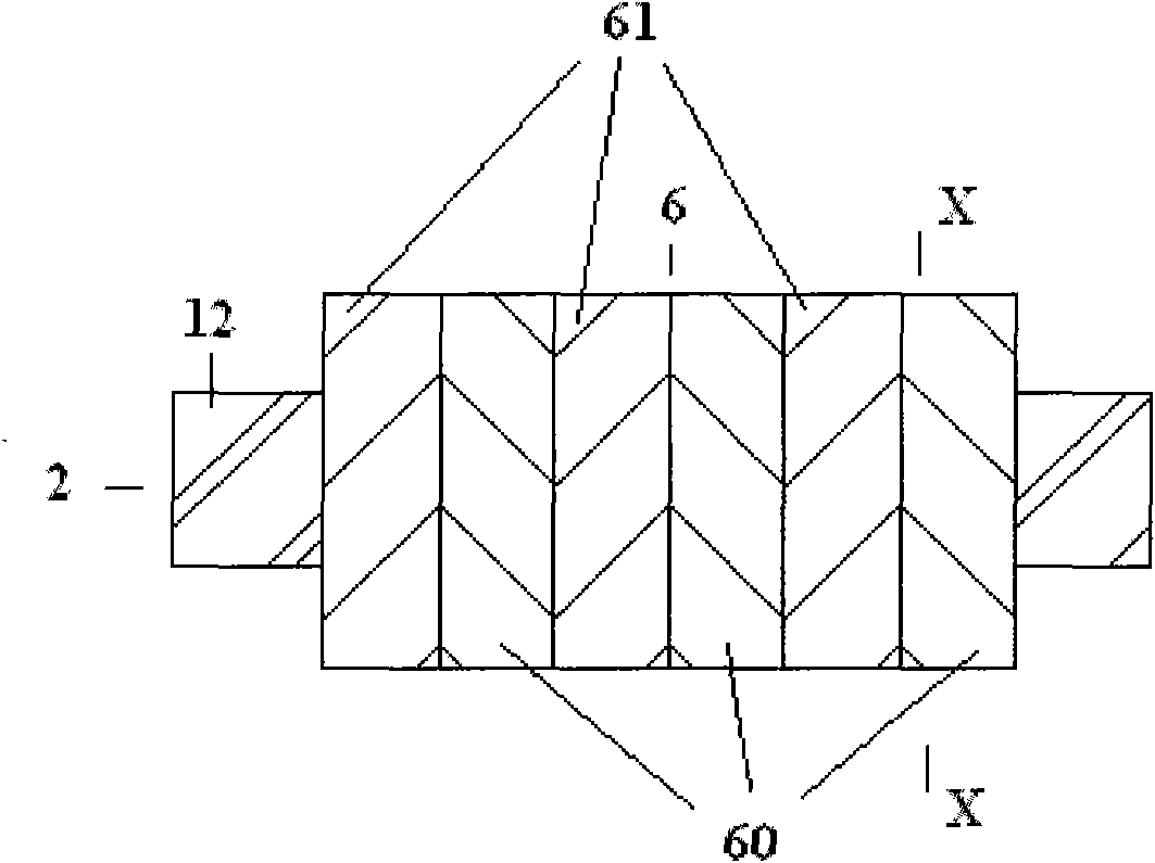
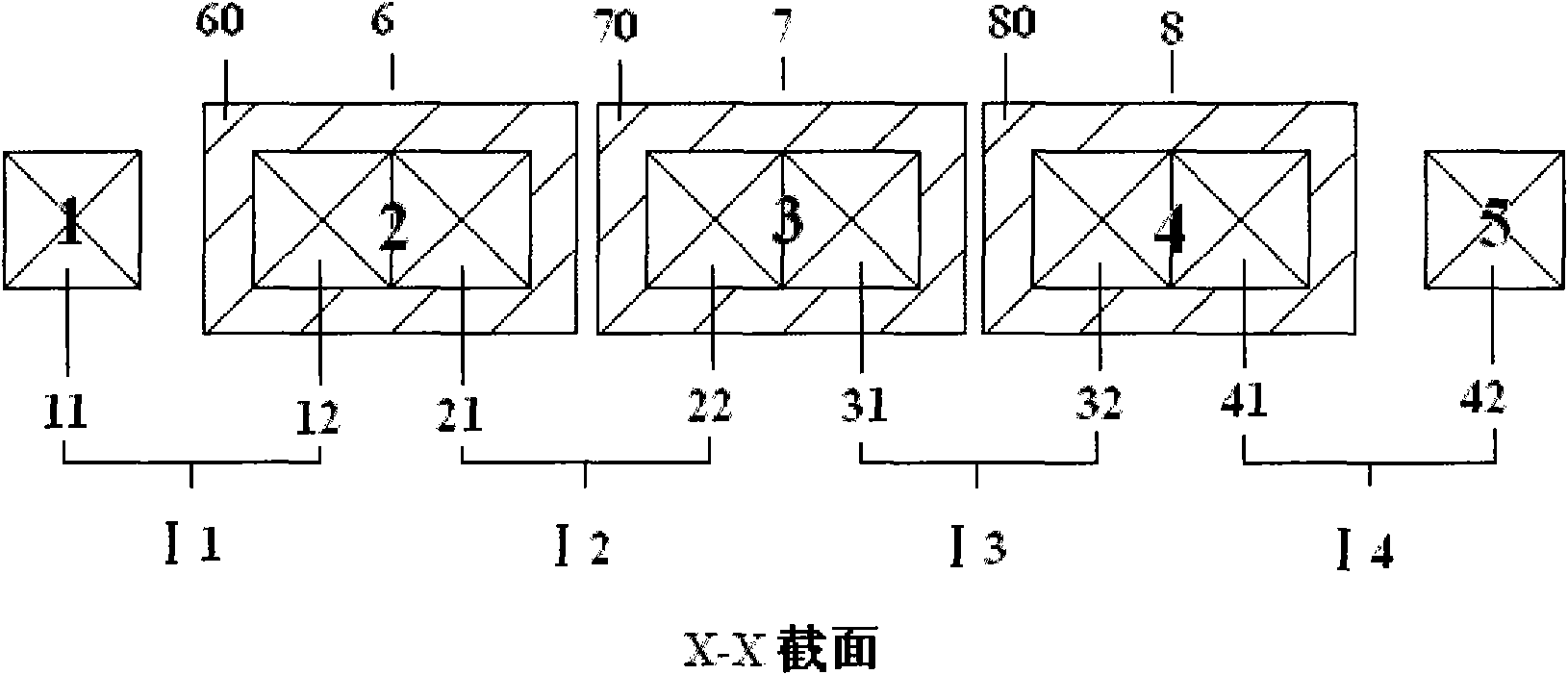
[0030] Embodiment 3 The third of the transformer body in which the iron core column is placed horizontally. The structure of this embodiment, see Figure 5 and Image 6 .
[0031] The five core columns are the first core column 1, the second core column 2, the third core column 3, the fourth core column 4 and the fifth core column 5, and the three windings are the first winding 6, the second winding 7 and the third winding 8, the first winding 6, the second winding 7 and the third winding 8 are respectively set on the second core 2, the third core 3 and the fourth core 4, the second core 2, the third The cross-sections of the three core columns 3 and the fourth core column 4 are rectangular, m=2, and the five core column iron cores are arranged in groups of four and 2 groups and stacked side by side in turn by eight O-shaped iron frames The four O-shaped iron frames are No. 1 O-shaped iron frame I1 of Group I, No. 2 O-shaped iron frame I2 of Group I, No. 3 O-shaped iron fra...
PUM
 Abstract
Description
Claims
Application Information