

Lead frame for manufacturing rectifier
A lead frame and rectifier technology, which is applied in the field of lead frames, can solve the problems of low utilization rate of copper materials, achieve the effects of improving utilization rate, avoiding instability, and reducing the probability of grain damage or poor contact
Inactive Publication Date: 2011-01-05
SUZHOU GOODARK ELECTRONICS CO LTD
View PDF7 Cites 1 Cited by
- Summary
- Abstract
- Description
- Claims
- Application Information
AI Technical Summary
Problems solved by technology
The purpose of the present invention is to provide a lead frame used for manufacturing rectifiers, which overcomes the problems of the prior art, such as strict requirements on flatness and low utilization rate of copper materials, greatly reduces the probability of crystal grain damage or poor contact and Improved copper utilization
Method used
View moreImage
Smart ImageViewing Examples

Examples
Embodiment
Login to View More PUM
 Abstract
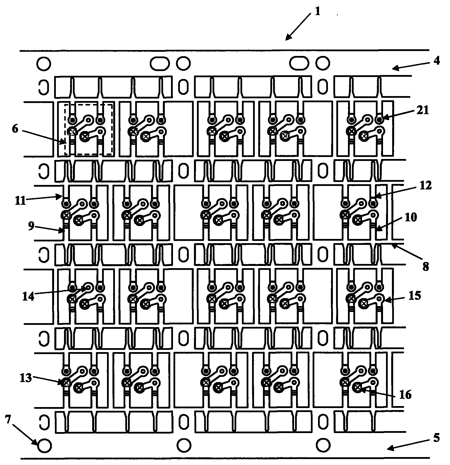
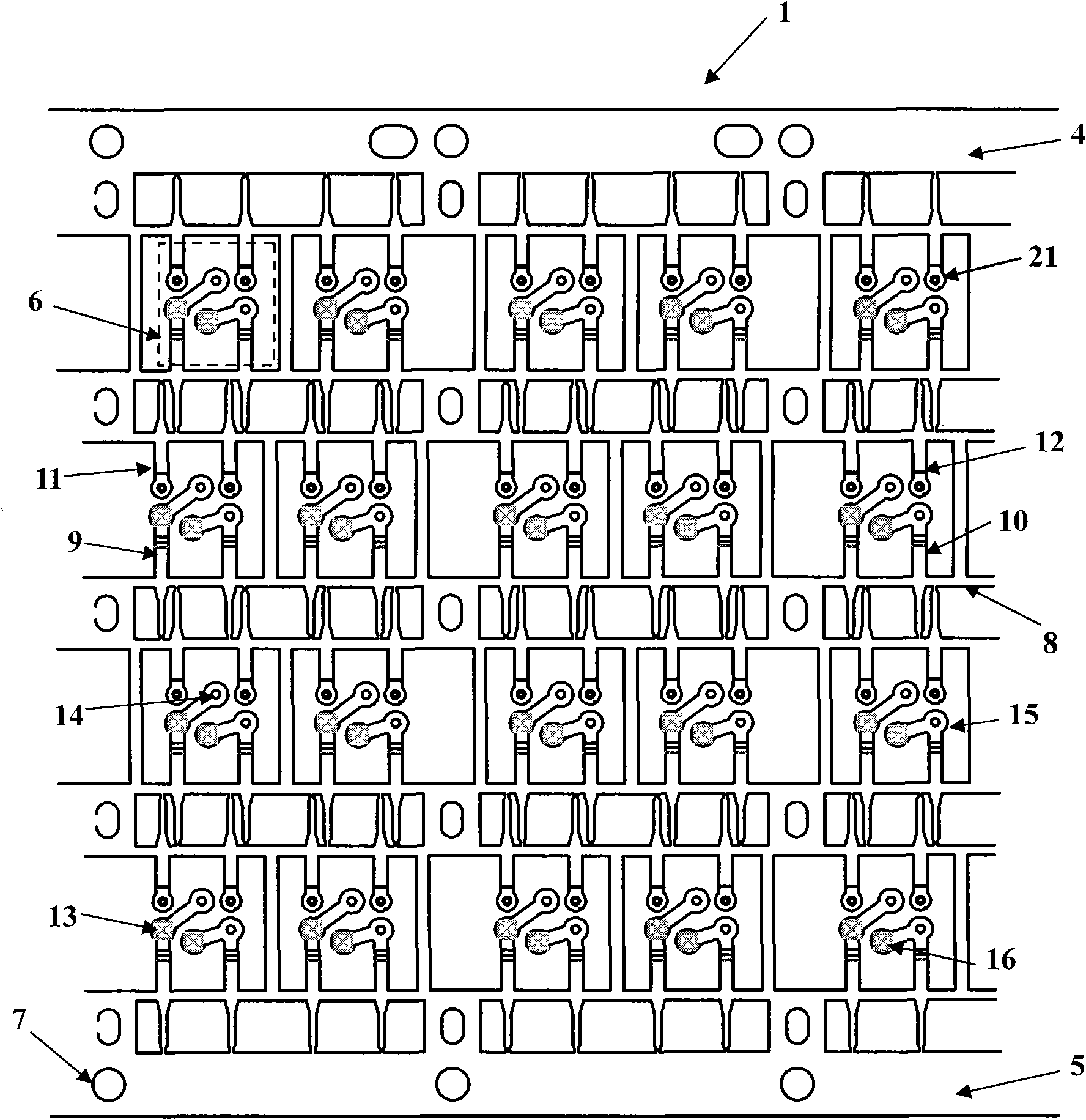
The invention relates to a lead frame for manufacturing a rectifier, comprising a supporting chip, a plurality of first connecting sheets and a plurality of second connecting sheets, wherein the supporting chip mainly comprises a first positioning pin, a second positioning pin and a plurality of chip welding zones, wherein the plurality of chip welding zones are positioned between the first positioning pin and the second positioning pin in an arrangement way of at least two rows and at least two lines; the first connecting sheets are provided with fifth welding point zones used for corresponding to first welding point zones and sixth welding point zones used for corresponding to fourth welding point zones; and the second connecting sheets are provided with seventh welding point zones used for corresponding to second welding point zones and eighth welding point zones used for corresponding to third welding point zones. The invention solves the problems of strict requirements for smoothness and low copper material utility ratio in the prior art, greatly reduces the probability of crystal grain damage or poor contact and enhances the copper material utility ratio.
Description
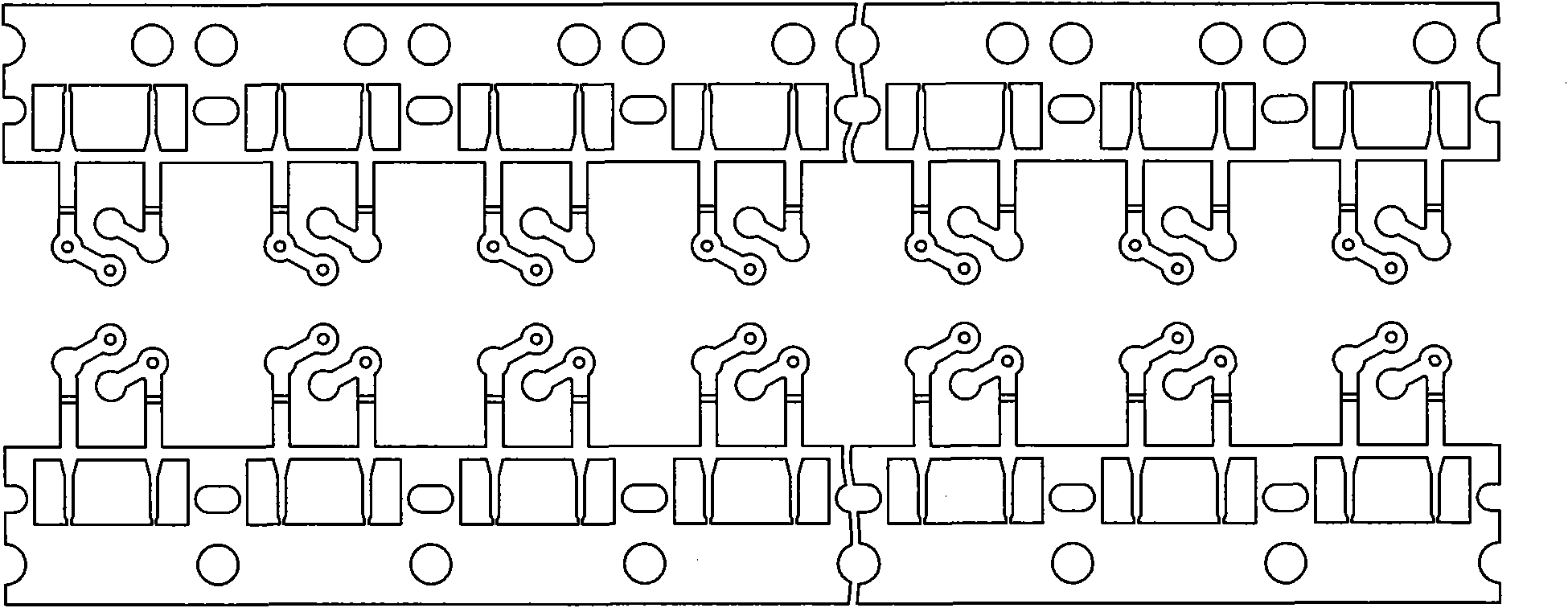
A lead frame for manufacturing a rectifier technical field The invention relates to a lead frame, in particular to a lead frame for manufacturing a rectifier. Background technique The bridge rectifier is a bridge structure composed of four rectifying diodes. It uses the unidirectional conduction characteristics of the diodes to rectify the alternating current. Since the utilization efficiency of the bridge rectifier for the input sine wave is twice as high as that of the wave rectification, it is suitable for A significant improvement of diode half-wave rectification, it is widely used in circuits that convert alternating current to direct current. The existing DF diode rectifier products are double-row laminated structure, with simple production process and easy operation. The lead frame and diode chip are soldered and packaged in an epoxy package. As shown in Figure 1, but the existing two-piece lead frame is often difficult to put all the diode grains in the best wel...
Claims
Login to View More Application Information
Patent Timeline
 IPC IPC(8): H01L23/495
CPCH01L2224/97
Inventor葛永明何洪运
OwnerSUZHOU GOODARK ELECTRONICS CO LTD