Heat pipe type high-power LED (Light Emitting Diode) module
A LED module, high-power technology, applied in electrical components, electrical solid devices, circuits, etc., to achieve the effect of reducing thermal resistance
Inactive Publication Date: 2011-01-05
HUNAN YOULI MEDICAL TECH
View PDF5 Cites 8 Cited by
- Summary
- Abstract
- Description
- Claims
- Application Information
AI Technical Summary
Problems solved by technology
In order to solve the above-mentioned technical problems existing in the heat dissipation of existing high-power LED chips, the present invention provides a heat pipe type high-power LED module with good heat dissipation effect
Method used
View moreImage
Smart ImageViewing Examples

Examples
Embodiment Construction
Login to View More PUM
 Abstract
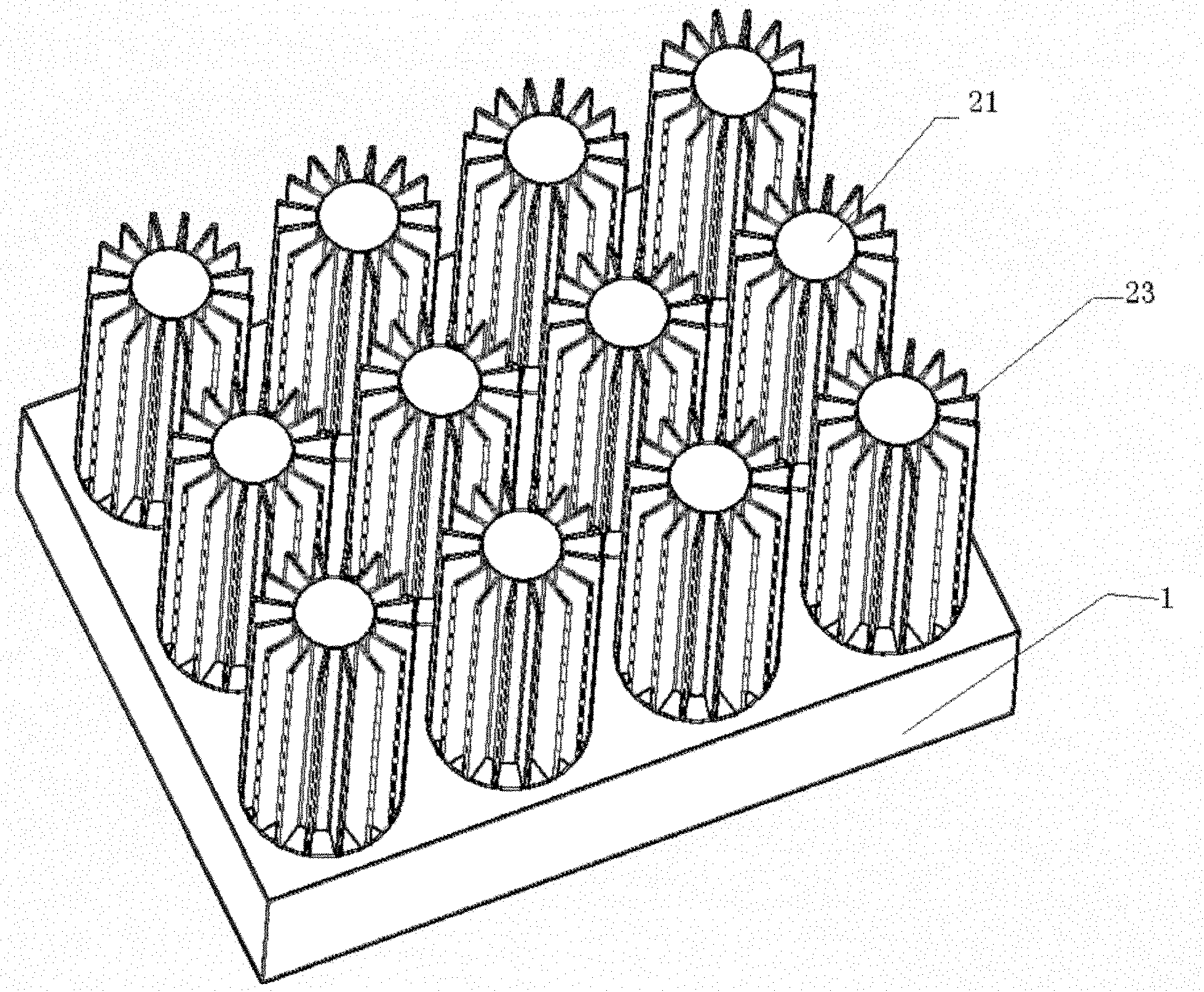
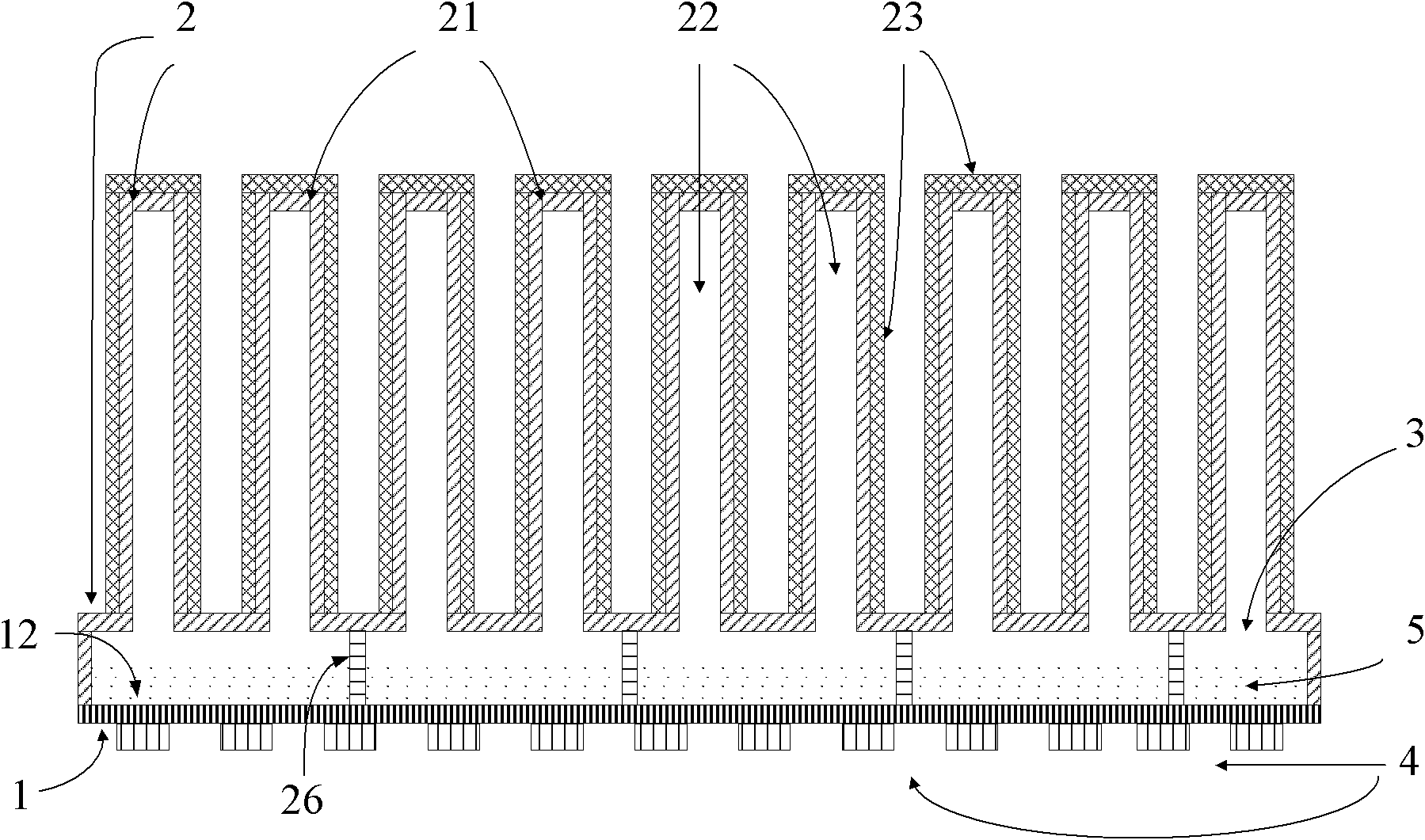
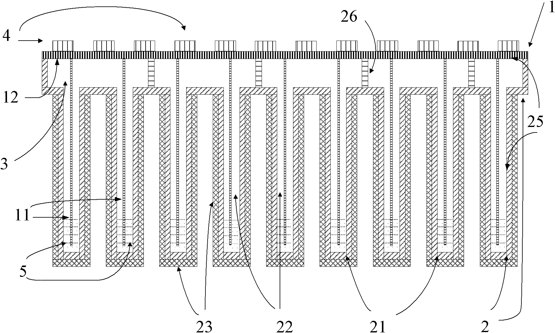
The invention relates to a heat pipe type high-power LED module. A closed cavity is formed by adopting a metal-base PCB (Printed Circuit Board) circuit board and a cavity wall, wherein a plurality of LED luminous chips are welded on the surface of the metal-base PCB circuit board, and latticed ribs are arranged on the inner wall of the metal-base PCB circuit board; the cavity wall comprises a plurality of radiating column bodies with hollow cavities, and a great quantity of radiating fins are arranged on the outer wall of each radiating column body. In the other implementation mode, the inner walls of the radiating column bodies and / or the metal-base PCB circuit board and the column surface of a supporting upright column are provided with capillary structures, the inner wall of the metal-base PCB circuit board is connected with a plurality of capillary columns, and the capillary columns extend into the hollow cavities of the radiating column bodies. The invention simultaneously realizes the functions of heating (lighting), transferring heat and radiating heat by using heat pipes and overcomes the defects that when the traditional high-power LED luminous chips work in a high-temperature environment, the heat radiation is difficult, and the service life and the reliability are greatly reduced. The invention is suitable for street lamps, tunnel lamps, projector lamps, stage lamps, and the like and other electronic devices manufactured by high-power LED modules.
Description
technical field [0001] The invention relates to an LED cooling device, in particular to a heat pipe type high-power LED module. Background technique [0002] Nowadays, the application of high-power electronic components is more and more extensive, so it is more and more important to solve the problem of heat dissipation. The fatal disadvantage of high-power LED light-emitting chips is that they work in a high-temperature environment, greatly reducing their service life and reliability, and greatly increasing their light attenuation. For white light emission, every time the LED chip junction temperature increases by 8-10°C, the working life of the device will decrease by about one time according to the exponential law. When the LED junction temperature exceeds 100°C, the failure rate of the device will rise exponentially, and the reliability will drop by 10% for every 2°C increase in the component temperature. Therefore, in order to ensure the life of the device, LED light...
Claims
Login to View More Application Information
Patent Timeline
 IPC IPC(8): H01L25/00H01L33/48H01L33/64
Inventor 陈小林任立宏谢中王祝盈蒋文科
Owner HUNAN YOULI MEDICAL TECH
Features
- Generate Ideas
- Intellectual Property
- Life Sciences
- Materials
- Tech Scout
- Unparalleled Data Quality
- Higher Quality Content
- 60% Fewer Hallucinations
Learn More Browse by: Latest US Patents, China's latest patents, Technical Efficacy Thesaurus, Application Domain, Technology Topic, Popular Technical Reports.
© 2025 PatSnap. All rights reserved.Legal|Privacy policy|Modern Slavery Act Transparency Statement|Sitemap|About US| Contact US: help@patsnap.com