Electro-pyrotechnic initiator and manufacturing method thereof

A technology of detonators and pyrotechnics, which can be used in blasting barrels, weapon accessories, vehicle parts, etc., and can solve problems such as poor leak-proof effects

Inactive Publication Date: 2011-01-12
AUTOLIV DEV AB
View PDF17 Cites 4 Cited by
  • Summary
  • Abstract
  • Description
  • Claims
  • Application Information

AI Technical Summary

Problems solved by technology

These second-type detonators are less leak-proof than first-type detonators, on the one hand due to the use of hygroscopic plastic materials such as polyamide, and on the other hand due to the connection of the metal electrodes to the plastic substrate, e.g. overmolding

Method used


Image

  • Electro-pyrotechnic initiator and manufacturing method thereof
  • Electro-pyrotechnic initiator and manufacturing method thereof
  • Electro-pyrotechnic initiator and manufacturing method thereof

Examples


Embodiment Construction

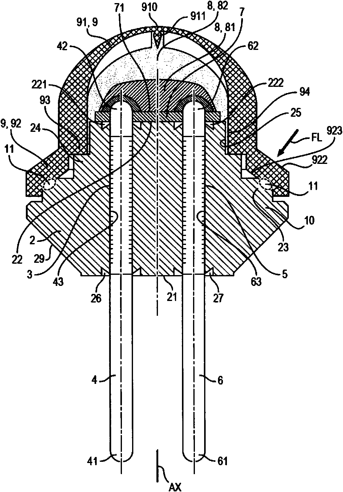
[0052] In the figures, the initiator 1 comprises a base 2 made of a first plastic material opaque to a laser beam having a defined wavelength. The base 2 comprises a first conduit 3 for insertion of a first electrode 4 and a second conduit 5 for insertion of a second electrode 6 . Pipeline 3 is different from Pipeline 5. Electrode 4 is different from electrode 6 . The electrodes 4 , 6 are electrically conductive and are, for example, metal. For example, the electrodes 4 , 6 are rectilinear and each formed by a metal pin, so that they can be cylindrical and have a circular cross section, for example.

[0053] The electrodes 4, 6 are inserted into the base 2 so that their respective first ends 41, 61 protrude from the first side 21 of the base 2 and their respective second ends 42, 62 protrude from the second side 22 of the base 2. protruding, the first end 41, 61 is used to connect to an external circuit for controlling the detonator, the second side 22 is different from the...


PUM


Abstract

The invention relates to an electro-pyrotechnic initiator, comprising a cap (9), a printed circuit plate (7) with a heating resistive element (71) turned toward a pyrotechnic load (8), electrodes (4, 6) connected to the element (71), and a substrate (2) supporting the plate (7), wherein the cap (9) comprises a part (92) adhered to the part (23) corresponding to the substrate (2). According to theinvention, a first part in the parts (23, 92) is plastic material opaque to a laser beam (FL) of determined wave length of welding, and the other part is made transparent plastic to the laser beam (FL) so as to transverse along direction to come across the first part by the laser beam (FL), thereby forming a zone (11) for welding parts (23, 92).

Description

technical field [0001] The invention relates to an electric pyrotechnic detonator and a manufacturing method thereof. Background technique [0002] These electrical pyrotechnic initiators are used in motor vehicles as pyrotechnic igniters for triggering gas generators that inflate inflatable airbags, or for triggering seat belt pretensioners. [0003] Such initiators typically include a cap that includes a pyrotechnic charge, a heat-resistant component that turns toward the pyrotechnic charge to ignite the pyrotechnic charge, and two electrodes. An electrode is electrically connected to the heat-resistant member to supply current thereto from the outside. [0004] A base is provided to support the entire device and to hermetically seal the cap. [0005] There are currently two types of detonators. [0006] The first type of initiator is provided with a glass sleeve for each electrode in a metal base. Such detonators ensure a good seal by means of a glass / metal seal and b...

Claims


Application Information

Patent Timeline
Patent Type & Authority Applications(China)
IPC IPC(8): B60R21/264
CPCF42B3/107F42B3/195
Inventor 西尔万·加里格克里斯托夫·加图阿米娜·哈米达扬·德卡斯泰克
Owner AUTOLIV DEV AB
Why Eureka
Try Eureka