Multistage compressor and oscillating piston

A technology for swinging pistons and compressors, applied to pistons, multi-stage pumps, cylindrical pistons, etc., can solve the problems that it is difficult to fully prevent the deformation of lip rings, and achieve the effect of small resistance and improved assembly

Active Publication Date: 2011-01-12
MAX CO LTD
View PDF4 Cites 7 Cited by
  • Summary
  • Abstract
  • Description
  • Claims
  • Application Information

AI Technical Summary

Problems solved by technology

Therefore, when the above-mentioned space becomes the largest, it is difficult to sufficiently prevent deformation of the lip ring

Method used


Image

  • Multistage compressor and oscillating piston
  • Multistage compressor and oscillating piston
  • Multistage compressor and oscillating piston

Examples


Embodiment Construction

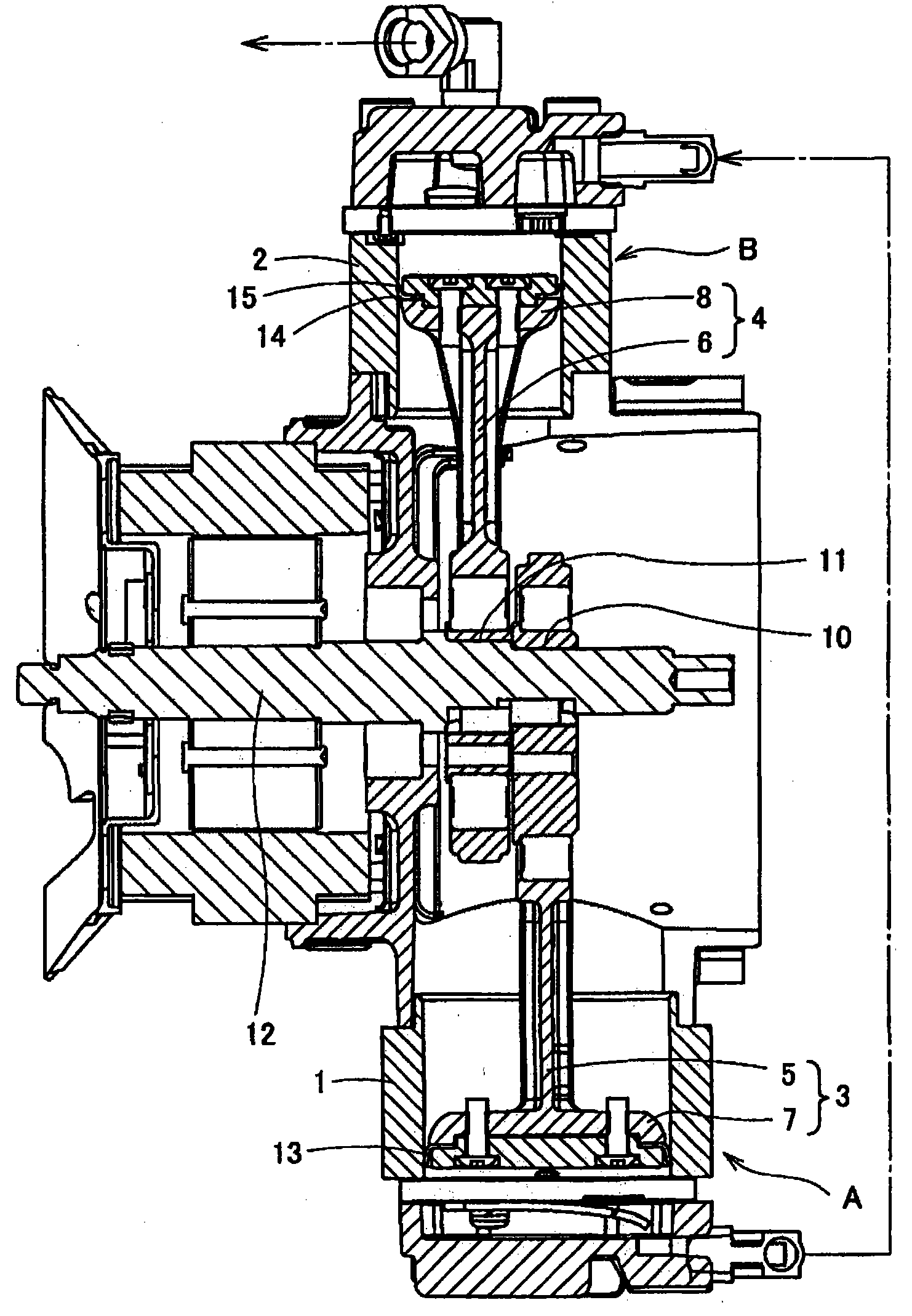
[0065] figure 1 Indicates a multi-stage (two-stage) compressor. This multi-stage compressor is formed by connecting a low-pressure compressor A and a high-pressure compressor B, and swing pistons 3 and 4 are housed in cylinders 1 and 2 of the compressors A and B so as to be able to swing and slide freely. In each of the swing pistons 3, 4, disc-shaped piston portions 7, 8 are integrally provided at the front ends (small end portions) of the connecting rods 5, 6. As shown in FIG. A crankshaft 12 disposed at the center of the device main body is supported by bearing holes 10 and 11 formed at eccentric positions of bases (big ends) of the connecting rods 5 and 6 . The crankshaft 12 is operationally connected by an unillustrated rotary drive device.

[0066] In the above-mentioned compressors A and B, the swing piston 3 of the compressor A on the low-pressure side (primary pressure) side reciprocates due to the rotation of the crankshaft 12, and the atmospheric air taken into th...


PUM


Abstract

The invention aims to provide a multistage compressor and an oscillating piston. The multistage compressor is provided with: a compressor for low pressure (A); a compressor for high pressure (B) connected with the compressor for low pressure (A); an oscillating piston (3) configured in the cylinder (1) of the compressor for low pressure (A) in sliding manner; and an oscillating piston (4) configured in the cylinder (1) of the compressor for high pressure (B) in sliding manner. The oscillating piston (4) of the compressor for high pressure (B) is provided with a lip seal (14), and the lip seal (14) is provided with a sealing part (15) contacted with the inner surface of the cylinder (2) at high pressure area and capable of being elastically deformed to have sealing effect.

Description

technical field [0001] The invention relates to a multi-stage compressor and a swinging piston which step up the pressure from low pressure to high pressure sequentially through a plurality of compressors. Background technique [0002] In the multi-stage compressor, air at atmospheric pressure is compressed by a compressor for low pressure, and then the compressed air is further compressed by a compressor for high pressure to increase the pressure to a high pressure. [0003] As a piston used in a compressor, a common cylindrical piston used in a reciprocating engine and the like, and a swing piston that reciprocates while swinging in a cylinder are known. The piston part of the cylindrical piston moves along the axis of the cylinder, so the operation is stable, but the structure is complicated and expensive. In contrast to this, the structure of the pivot piston is simple and relatively inexpensive. However, since the rocking piston has a structure in which the piston par...

Claims


Application Information

Patent Timeline
IPC IPC(8): F04B39/00F04B25/00F16J15/32F16J1/14F04B41/06
Inventor 浅井正敏福本纮之
Owner MAX CO LTD
Why Eureka
Try Eureka