Temperature-measurement imaging system and measuring method thereof

An imaging system and measurement method technology, applied in the direction of measuring devices, optical radiation measurement, radiation pyrometry, etc., can solve the problems of high cost, poor synchronization of multiple imaging components, and increase the cost of the temperature measurement system, so as to reduce the impact, The effect of improving accuracy

Active Publication Date: 2011-09-07
卢家金
View PDF0 Cites 1 Cited by
  • Summary
  • Abstract
  • Description
  • Claims
  • Application Information

AI Technical Summary

Problems solved by technology

The advantage of this type of temperature measurement imaging system is that it can measure lower temperatures, even including objects at room temperature. The disadvantage is that the cost is high, mainly because the cost of infrared imaging photosensitive elements is much higher than that of other visible light and near-infrared imaging elements.
[0003] In recent years, most CCD-based temperature measurement and imaging systems are based on multiple CCD cameras or multiple CCD elements. The radiation signal is split into multiple CCD cameras, and the temperature calculation is performed using the principle of radiation temperature measurement. This makes the temperature measurement system more complicated. At the same time, due to The synchronization difference problem caused by multiple imaging components increases the difficulty of system calibration and calibration, and also increases the cost of the temperature measurement system

Method used


Image

  • Temperature-measurement imaging system and measuring method thereof
  • Temperature-measurement imaging system and measuring method thereof
  • Temperature-measurement imaging system and measuring method thereof

Examples


Embodiment Construction

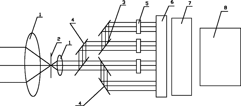
[0026] Such as figure 1 As shown, the system of the present invention includes the following components along the optical path:

[0027] 1) Optical lens group: Including convex lens 1 and noise reduction aperture 2. According to the size of the object and the requirements for image magnification, the number of convex lenses 1 can be adjusted. figure 1 It expresses two convex lenses. The optical lens group collects, reduces noise and collimates the radiation signal on the surface of the object to be measured;

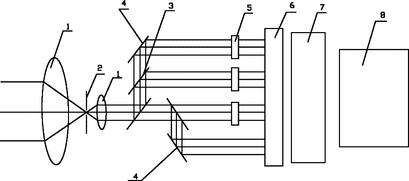
[0028] 2) Dichroic prism and reflecting mirror group: including the dichroic prism 3 and the plane mirror 4, the optical signal after passing through the optical lens group is divided into at least two groups of signals, figure 1 with figure 2 It expresses the division of light signals into four groups of signals, where figure 1 It expresses 3 beam splitting prisms 3 and 3 plane mirrors 4, figure 2 It expresses three beam splitting prisms 3 and two flat mirrors 4, and the sig...


PUM


Abstract

The invention provides a low-cost temperature-measurement imaging system avoiding the problem of synchronous difference brought by a plurality of imaging elements. The temperature-measurement imaging system comprises an optical lens group, a dispersion prism and reflection mirror group, imaging elements and a signal processor along an optical path; an optical filter group is arranged before the imaging elements and comprises at least two groups of optical filters; the number of the optical filter groups is one less than the number of optical signal groups after passing through the dispersion prism and reflection mirror group; and the imaging elements are signal-chip single-color CCD (Charge-Coupled Device) or CMOS (Complementary Metal-Oxide Semiconductor) imaging elements. In the invention, on the basis of the thermogenic radiation of an object, the non-contact system and the non-contact method can be used for comparing a plurality of signals so as to detect a temperature-measurement boundary of the object, calculating the surface temperature of the detected object by using a multiband thermogenic radiation temperature algorithm and system characteristics and can also be used for carrying out the two-dimensional characterization on a temperature field of the surface of the object to be measured. The invention can be conveniently applied to various high-temperature fields.

Description

Technical field [0001] The invention relates to a temperature measurement imaging system and a measurement method thereof. Background technique [0002] The current common temperature measurement imaging system is mainly based on infrared photosensitive elements, and its structure mainly includes an optical lens, an infrared imaging photosensitive element, and a signal processing unit. The wavelength of the sensing light of the photosensitive element is usually above 1 micron. The advantage of this type of temperature measurement imaging system is that it can measure lower temperatures, even including objects at room temperature. The disadvantage is that the cost is higher. This is mainly because the cost of the infrared imaging sensor is much higher than other visible and near-infrared imaging elements. [0003] In recent years, CCD-based temperature measurement imaging systems are mostly based on multiple CCD cameras or multiple CCD elements, which split the radiation signal to m...

Claims


Application Information

Patent Timeline
Patent Type & Authority Patents(China)
IPC IPC(8): G01J5/08G01J5/06
Inventor 卢家金
Owner 卢家金
Why Eureka
Try Eureka