
On-line corrosion detector for reinforced concrete and method thereof

A technology for reinforced concrete and steel bar corrosion, applied in weather resistance/light resistance/corrosion resistance, instruments, measuring devices, etc., can solve problems such as difficult to determine the polarization area of ​​steel bars, large deviation of results, far away from the real value, etc., to improve measurement Accuracy, easy operation, and the effect of improving accuracy

Inactive Publication Date: 2011-01-12
HUAZHONG UNIV OF SCI & TECH
View PDF3 Cites 33 Cited by
  • Summary
  • Abstract
  • Description
  • Claims
  • Application Information

AI Technical Summary

Problems solved by technology

[0004]The key to the corrosion detection of concrete reinforcement is to determine the polarization area of ​​the reinforcement as the working electrode, because all the reinforcement in the engineering structure are interconnected by the reinforcement, forming a It is difficult to determine the polarization area of ​​steel bars in actual engineering
In this regard, someone proposed the guard ring electrode method (Guard Ring electrode method, GRM) to constrain the polarization current of the auxiliary electrode, so that the polarization area is limited to a specific range, but this technology is based on complete current constraints and is not based on concrete Resistivity and steel corrosion state are adaptively adjusted, resulting in frequent over-constraint or under-constraint of current in field tests
U.S. Patent 5,259,944 is a patent on corrosion monitoring of grommet electrodes. Its internal circuit adopts full compensation mode, and does not automatically adjust the current constraints of grommet electrodes according to different concrete systems. The results measured during supervision have large deviations and are far from the true value

Method used


Image

  • On-line corrosion detector for reinforced concrete and method thereof
  • On-line corrosion detector for reinforced concrete and method thereof
  • On-line corrosion detector for reinforced concrete and method thereof

Examples


Embodiment Construction

[0024] The present invention will be described in further detail below in conjunction with the accompanying drawings and specific embodiments.

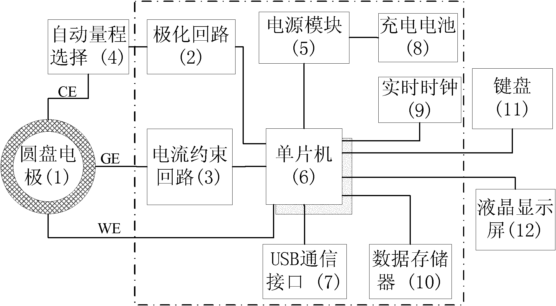
[0025] See attached figure 1 , The on-line detector for reinforced concrete corrosion of the present invention includes: a guard ring disk electrode 1 , a polarization circuit 2 , a current restraint circuit 3 , and a single-chip microcomputer 6 .

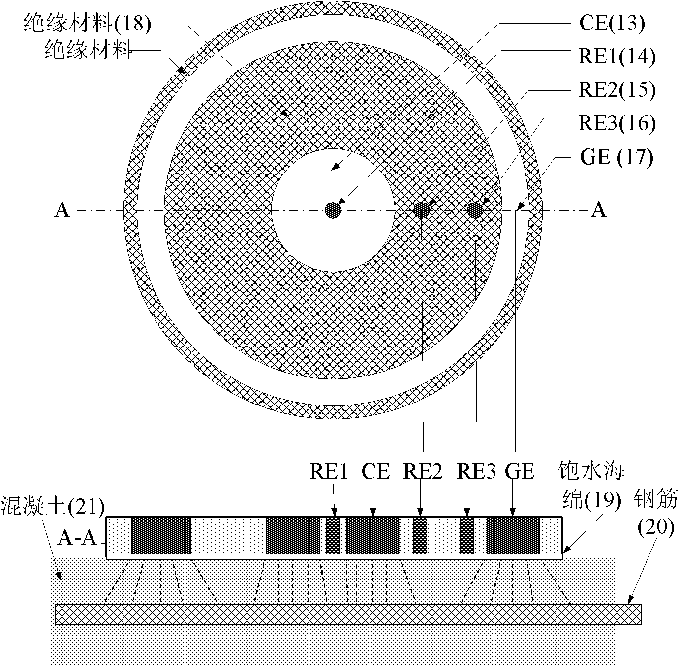
[0026] Such as figure 2 As shown, the guard ring disc electrode is used for the confinement of the polarization current, and the guard ring disc electrode includes 3 reference electrodes RE1, RE2, RE3 (by saturated Cu / CuSO 4 , Ag / AgCl or MnO 2 Electrode composition), an auxiliary electrode CE and a ring electrode GE, CE and GE electrodes are coaxially placed and embedded in an insulating disc, and there is a small hole with a diameter of 1-5mm in the center of the CE electrode for placing the reference electrode RE1 , the two form the input end of the polarization circuit together with...


PUM


Abstract

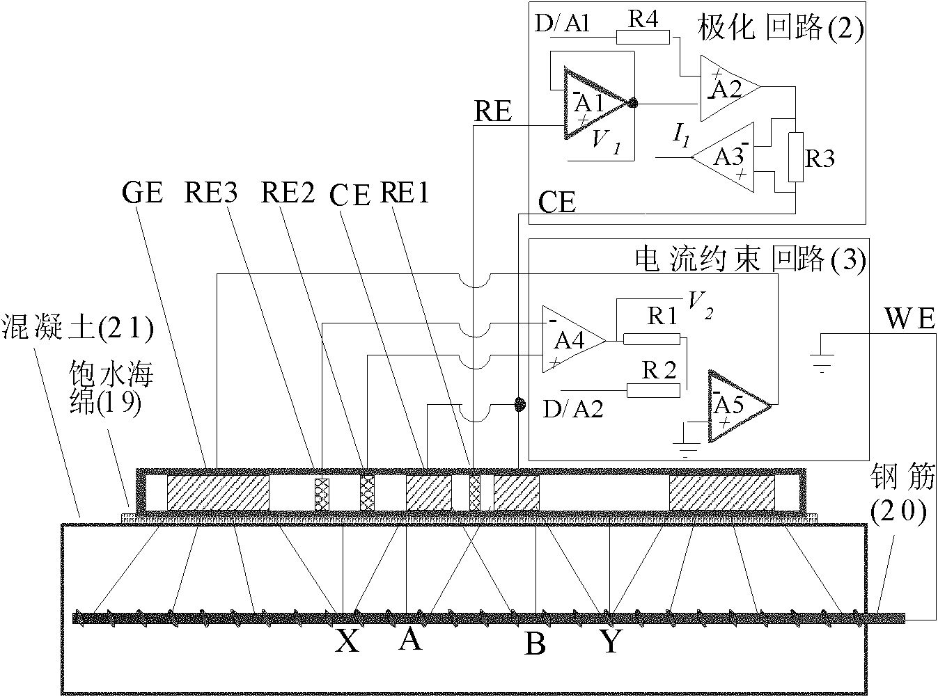
The invention provides an on-line corrosion detector for reinforced concrete based on a disk electrode. The on-line detector comprises a polarization circuit (2) and a current constraint circuit (3), wherein the disk electrode (1) comprises reference electrodes RE1, RE2 and RE3, an auxiliary electrode CE (13) and a circular ring electrode GE (17); the polarization circuit (2) polarizes the reinforcing steel bars in concrete through the auxiliary electrode CE (13) and the reference electrode RE1 in the disk electrode (1); and meanwhile the current constraint circuit (3) restrains polarization current through the circular ring electrode GE (17) and potential difference between the reference electrodes RE2 and the reference electrodes RE3 so as to limit the polarization current in a projection zone of the auxiliary electrode CE (13). The invention further provides a method for measuring corrosion rate of the reinforcing steel bar in a concrete structure by using the detector. The invention improves measurement accuracy of the corrosion rate of the reinforcing steel bars in the concrete structure and avoids measurement errors caused by current over-constraint and under-constraint.

Description

technical field [0001] The invention relates to the field of on-line corrosion detection of reinforced concrete, in particular to an on-line corrosion detector for reinforced concrete based on self-adaptive current constraints, which is a portable corrosion detector that directly measures the corrosion state of steel bars in the concrete structure without destroying the concrete structure. It is suitable for corrosion investigation of built concrete projects, online evaluation of rust inhibitor efficiency and cathodic protection effect. Background technique [0002] The health status of reinforced concrete is directly related to the safety and durability of large-scale building structures such as bridges, docks, and highways. Therefore, on-line monitoring of the corrosion status of steel bars has become a very important engineering problem. Early failure of concrete structures is caused by Cl - It is caused by ion intrusion and concrete carbonation, while steel corrosion is...

Claims


Application Information

Patent Timeline
Patent Type & Authority Applications(China)
IPC IPC(8): G01N17/02
Inventor 董泽华吴成郭兴蓬
Owner HUAZHONG UNIV OF SCI & TECH
Learn More