Working method for DFB laser-based XFP optical module for transmission

A DFB laser and optical module technology, applied in lasers, laser parts, semiconductor lasers, etc., can solve the problems of high power consumption and increased power consumption of optical modules, so as to improve yield, reduce power consumption, and improve switching rate. Effect

Active Publication Date: 2011-01-12
SOURCE PHOTONICS CHENGDU
View PDF3 Cites 23 Cited by
  • Summary
  • Abstract
  • Description
  • Claims
  • Application Information

AI Technical Summary

Problems solved by technology

In addition, due to the high power consumption of temperature controllers currently on the market, especially their

Method used


Image

  • Working method for DFB laser-based XFP optical module for transmission
  • Working method for DFB laser-based XFP optical module for transmission

Examples


Embodiment Construction

[0011] Any feature disclosed in this specification (including any appended claims, abstract and drawings), unless expressly stated otherwise, may be replaced by alternative features which are equivalent or serve a similar purpose. That is, unless expressly stated otherwise, each feature is one example only of a series of equivalent or similar features.

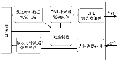
[0012] The XFP optical module for high-speed and low-power long-distance transmission of this embodiment, such as figure 1 As shown, it includes the electrical interface, the optical fiber input and output interface, the DFB laser component in the XFP optical module and the photodetector component, and also includes the DML laser driver module connected between the XFP optical module electrical interface and the DFB laser component for driving DFB laser assembly; also includes a microcontroller for implementing the functions of the module.

[0013] The output optical power of the DFB laser component is controlled by the auto...


PUM


Abstract

The invention discloses a method and optimization for adjusting an XFP optical module which adopts a distributed feedback (DFB) semiconductor laser by the gradual change of a digital potentiometer DAC and making the XFP optical module work at the best working point. The method and the optimization are suitable for a high-speed low-power consumption long-distance transmission optical fiber communication system; a microcontroller adjusts an APC control circuit through lookup tables (LUTs) to compensate bias current Ibias so as to make the set output light power of the DFB laser component the set output light power value which corresponds to the temperature range, and stabilizes the temperature of the DFB laser within the set output light power range through the APC control circuit; and the invention discloses a method for testing through two LUTs and three temperature points, and makes the XFP optical module which adopts the distributed feedback (DFB) semiconductor laser work under the best condition.

Description

technical field [0001] The invention relates to the field of photoelectric conversion devices in optical fiber data communication and telecommunication, in particular to an XFP optical module for high-speed, low-power and long-distance transmission. Background technique [0002] As the core device of the optical fiber communication network, the optical module promotes the development of the trunk optical transmission system in the direction of low cost, large capacity and low power consumption, making the configuration of the optical network more complete and reasonable, and the volume is getting smaller and smaller. The density is getting higher and higher. The optical module is composed of structural parts such as optoelectronic devices, functional circuits and photoelectric interfaces. The optoelectronic devices include two parts: transmitting and receiving: for different applications, the transmitting part includes several light sources such as LED, VCSEL, FP, DFB, and E...

Claims


Application Information

Patent Timeline
IPC IPC(8): H01S5/068H01S5/026
Inventor 彭奇黄庆朱富
Owner SOURCE PHOTONICS CHENGDU
Why Eureka
Try Eureka