
Filter compensation device of monocrystalline silicon furnace power supply

A technology of compensation device and silicon furnace, applied in the direction of harmonic reduction device, reactive power compensation, reactive power adjustment/elimination/compensation, etc., can solve the problems of reduced reliability, mechanical noise, long production cycle, etc., and achieve the goal of manufacturing The effect of improving the efficiency of installation, reducing the time of downtime, and reducing the loss of downtime

Inactive Publication Date: 2013-05-29
常州金坛金凯成套电控设备有限公司
View PDF5 Cites 0 Cited by
  • Summary
  • Abstract
  • Description
  • Claims
  • Application Information

AI Technical Summary

Problems solved by technology

However, the most primitive relay control is used in its control system. This control method is not only outdated, but also has a complicated manufacturing process (increasing production costs). Since the relay is mechanical, there is a certain time for opening and closing, which affects the equipment. control characteristics
When the relay is used for a long time, the mechanical moving parts will wear out, which will greatly reduce the reliability of the control, and will generate mechanical noise, polluting the production environment
Short life and high failure rate are also the Achilles heel of relays
It is unrealistic to use this traditional control method to improve the control performance of the equipment
Secondly, in the production and manufacture of traditionally controlled filter compensation cabinets, the manufacturing process is relatively complicated, there are many external interlocking connections, the wiring is prone to errors, and the production cycle is long and the production efficiency is relatively low.

Method used


Image

  • Filter compensation device of monocrystalline silicon furnace power supply
  • Filter compensation device of monocrystalline silicon furnace power supply
  • Filter compensation device of monocrystalline silicon furnace power supply

Examples


Embodiment Construction

[0017] Below in conjunction with accompanying drawing and embodiment the present invention is described in detail:

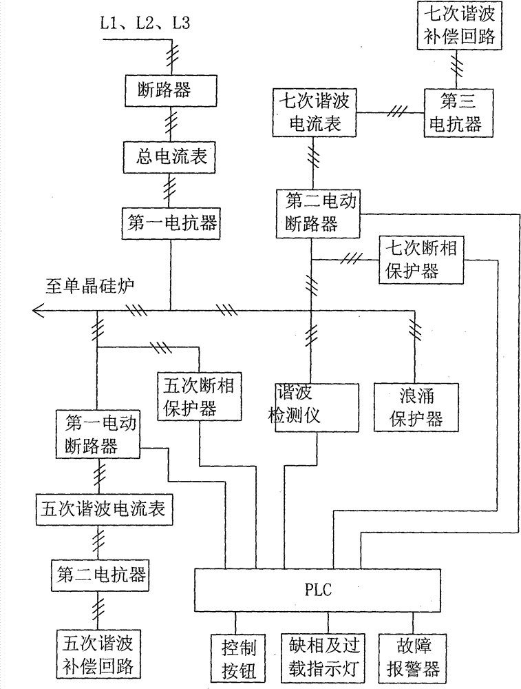
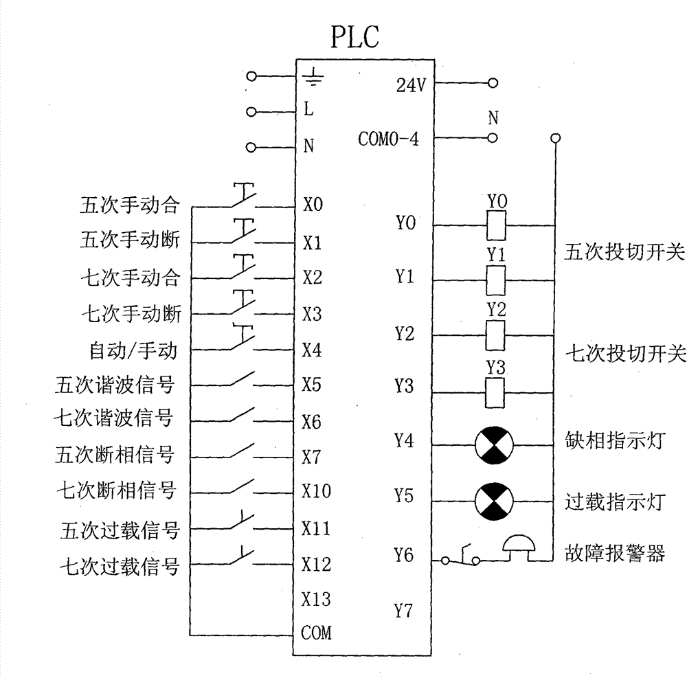
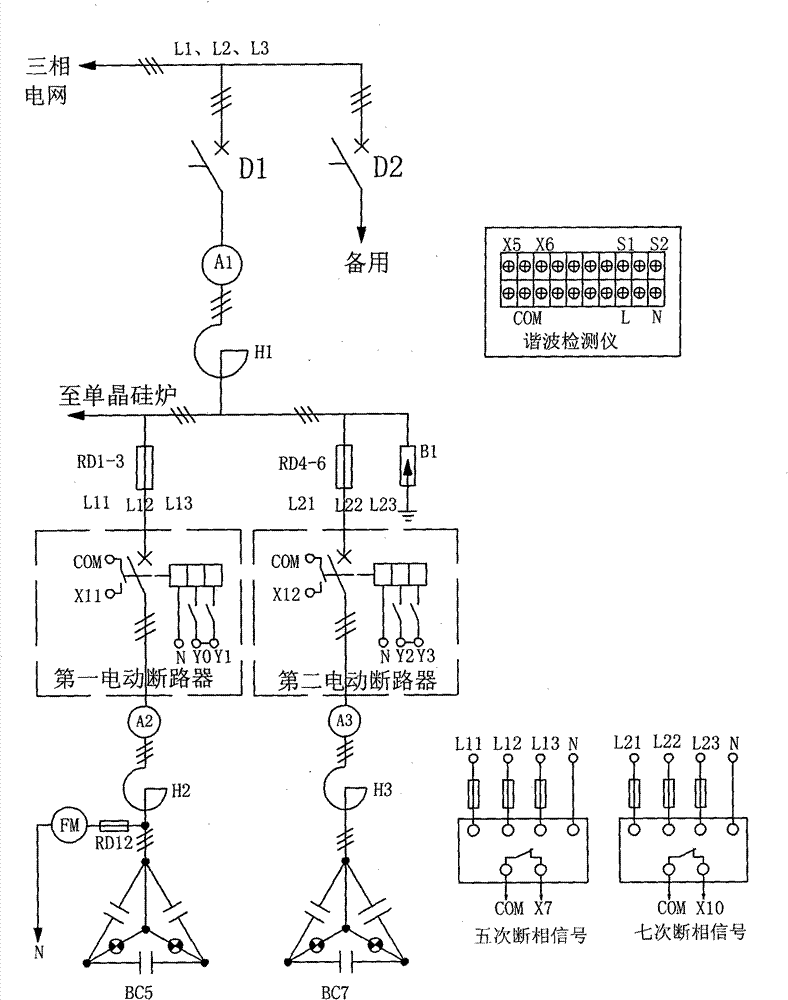
[0018] like Figure 1-3 , the monocrystalline silicon furnace power supply filter compensation device of this embodiment includes: figure 1 or L1, L2, L3 in 3) connected to the circuit breaker D1, and the first reactor H1 connected to the power supply output end of the circuit breaker D1; the current output end of the first reactor H1 is connected to the first motorized circuit breaker, the second The second electric circuit breaker, the fifth phase failure protector, the seventh phase failure protector are connected to the power supply terminal of the harmonic detector, the fifth phase failure signal output terminal of the fifth phase failure protector, and the seventh phase failure protector The seventh phase failure signal output terminal, the fifth and seventh harmonic signal output terminals of the harmonic detector are connected to the PLC; the current ou...


PUM


Abstract

The invention relates to a filter compensation device of a monocrystalline silicon furnace power supply, which has simple structure, is suitable for effectively inhabiting fifth and seventh harmonic waves, can improve the trouble shooting efficiency and comprises a breaker and a first reactor, wherein the breaker is connected with a three-phase electric network, and the first reactor is connectedwith the breaker; the first reactor is connected with a first electric breaker, a second electric breaker, a fifth open-phase protector, a seventh open-phase protector and a harmonic detector, and the fifth open-phase protector, the seventh open-phase protector and the harmonic detector are connected with a PLC (Programmable Logic Controller); the first electric breaker is connected with a secondreactor, and the second reactor is connected with a fifth harmonic compensation loop; the second electric breaker is connected with a third reactor, and the third reactor is connected with a seventh harmonic compensation loop; the first electric breaker and the second electric breaker are connected with the PLC; and the first reactor is used for being connected with the power supply end of a monocrystalline silicon furnace.

Description

technical field [0001] The invention relates to the technical field of power supply filter compensation, in particular to a filter compensation device for a single crystal silicon furnace power supply. Background technique [0002] The power supply of the existing monocrystalline silicon furnace is controlled by thyristor. Although this kind of control is advanced in technology, it produces a large number of harmonics that are fed back to the power grid. If no measures are taken for these harmonics, it will seriously affect the safety of the power grid. operation, and have many side effects on other electrical equipment, such as: the output of the motor is not enough to reach the designed power, and when the current increases seriously, it will be burned for no reason, and the loss of the power supply line will increase, which will increase the production cost of the enterprise ( increase in electricity bills), etc. [0003] Among the higher harmonics generated by monocryst...

Claims


Application Information

Patent Timeline
Patent Type & Authority Patents(China)
IPC IPC(8): H02J3/01H02J3/18
CPCY02E40/30Y02E40/40
Inventor 朱强
Owner 常州金坛金凯成套电控设备有限公司
Learn More