
Direct current step-up/step-down circuit

A technology of buck-boost circuit and DC bus, which is applied in the direction of circuit devices, battery circuit devices, collectors, etc., can solve the problems of reduced system equalization effect, low power transfer efficiency, and many times of power conversion, so as to improve energy transfer efficiency , Convenient system maintenance, eliminate the effect of conduction pressure drop loss

Inactive Publication Date: 2011-01-12
上海同异动力科技有限公司
View PDF4 Cites 10 Cited by
  • Summary
  • Abstract
  • Description
  • Claims
  • Application Information

AI Technical Summary

Problems solved by technology

The main disadvantages of the isolation transformer method are low power transfer efficiency, many circuit components, complex modules, high cost and low reliability
The disadvantage of the step-by-step transfer method is that the number of electric energy conversions is large, the energy loss is large, and the equalization efficiency is low.
At the same time, because electric energy is transmitted step by step, if a module fails, the equalization effect of the entire system will be significantly reduced, and the reliability of the system will be poor.

Method used


Image

  • Direct current step-up/step-down circuit
  • Direct current step-up/step-down circuit
  • Direct current step-up/step-down circuit

Examples


Embodiment Construction

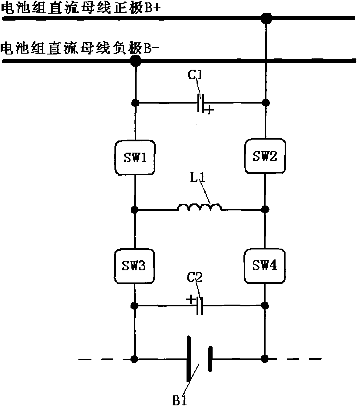
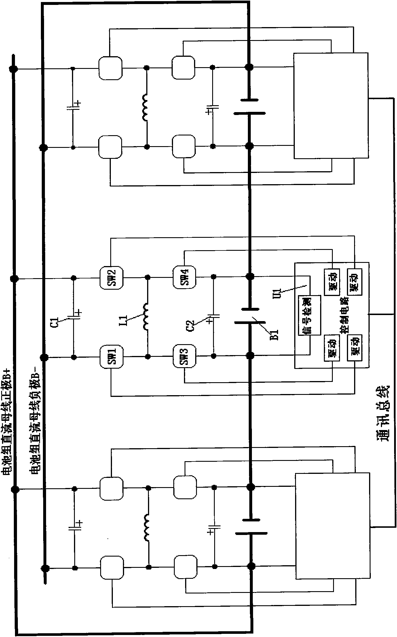
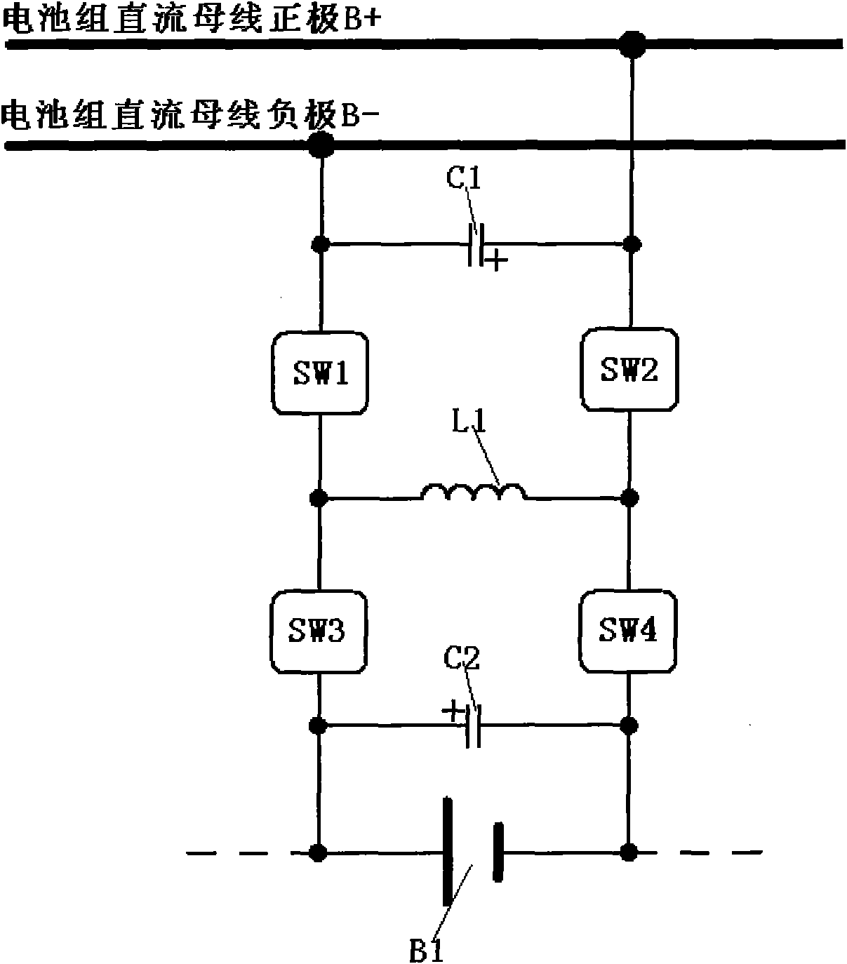
[0020] figure 1 It is a block diagram of the principle of the present invention. A DC buck-boost circuit is shown in the figure, including the DC bus bar of the battery pack, battery cells and switching devices, characterized in that: the positive pole of the battery cell B1 is connected to one end of the third switching device SW3, and the other end of the third switching device SW3 is connected to the storage One end of the energy storage inductor L1 and one end of the first switching device SW1, the other end of the energy storage inductor L1 is connected to one end of the second switching device SW2 and one end of the fourth switching device SW4, and the other end of the fourth switching device SW4 is connected to the battery Negative terminal of unit B1. The other end of the first switching device SW1 is connected to the negative pole of the DC bus bar of the battery pack, and the other end of the second switching device SW2 is connected to the positive pole of the DC bu...


PUM


Abstract

The invention discloses a direct current step-up / step-down circuit. The direct current step-up / step-down circuit is characterized in that: an anode of a battery unit is connected with one end of a third switching device; the other end of the third switching device is connected with one end of an energy storage inductor and one end of a first switching device; the other end of the energy storage inductor is connected with one end of a second switching device and one end of a fourth switching device; the other end of the fourth switching device is connected with a cathode of the battery unit; the other end of the first switching device is connected with a direct current bus cathode of a battery set; the other end of the second switching device is connected with a direct current bus anode of the battery set; and the states of the first, second, third and fourth switching devices are controlled by a control circuit (U1). The step-up operation or step-down operation of a direct current power supply is realized by controlling the on / off timing sequence of corresponding switching devices. The direct current step-up / step-down circuit has the advantages of flexible control of step-up / step-down proportion, independent working of modules, simple structure, low cost, high efficiency, high reliability and capability of realizing standard and batch production.

Description

technical field [0001] The invention belongs to the technical field of DC voltage-boosting circuits, in particular to a voltage-boosting circuit for electric balance of series battery packs, and in particular to a voltage-boosting circuit for non-energy consumption real-time balancing technology of power battery packs. Background technique [0002] With the application of batteries with large capacity density and high power density becoming more and more common, the balancing technology of battery packs has become the main task of the battery management system. Currently the most widely used lead-acid batteries, nickel metal hydride batteries and lithium-ion batteries, due to differences in the production process, performance changes during use and other factors, there are inconsistencies between unit batteries that cannot be completely eliminated. [0003] When the battery pack is used in occasions that require frequent charge and discharge cycles, such as electric vehicles...

Claims


Application Information

Patent Timeline
Patent Type & Authority Applications(China)
IPC IPC(8): H02J7/00H02M3/135
Inventor 张翼胡联庆
Owner 上海同异动力科技有限公司
Learn More