
Permanent magnet linear reciprocating mechanism

A reciprocating mechanism and permanent magnet linear technology, applied in the direction of electromechanical devices, electrical components, etc., can solve the problems of low energy conversion efficiency, many parts, affecting working life and reliability, etc., and achieve simple structure and reliability High, improve the effect of system life and reliability

Active Publication Date: 2011-01-12
NINGBO INST OF MATERIALS TECH & ENG CHINESE ACADEMY OF SCI
View PDF4 Cites 21 Cited by
  • Summary
  • Abstract
  • Description
  • Claims
  • Application Information

AI Technical Summary

Problems solved by technology

The linear reciprocating motion mechanism generally uses a rotating motor plus a screw or a crank connecting rod to convert the rotating motion of the rotating motor into a linear motion. However, this working method not only has low energy conversion efficiency, but also has a complex mechanism and many parts. high failure rate
Linear motors can directly generate linear reciprocating motion, but multiple sets of coils are required to generate traveling wave magnetic fields. For fast linear reciprocating motion with small strokes, the drive control device is complicated and does not have the function of maintaining the end position.
In addition, the wear and tear of moving parts will also affect the working life and reliability

Method used


Image

  • Permanent magnet linear reciprocating mechanism
  • Permanent magnet linear reciprocating mechanism
  • Permanent magnet linear reciprocating mechanism

Examples


Embodiment Construction

[0013] The present invention will be further described below in conjunction with the accompanying drawings and embodiments.

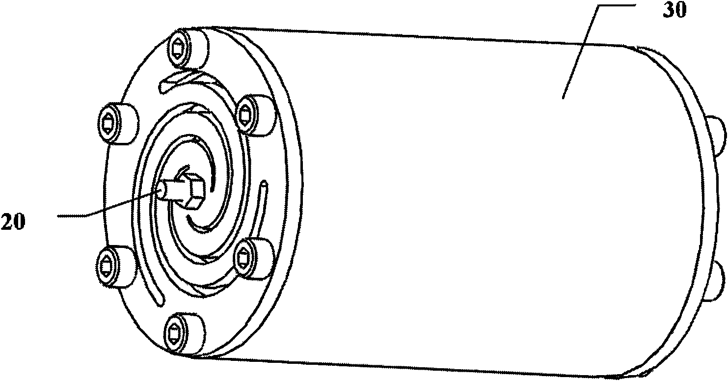
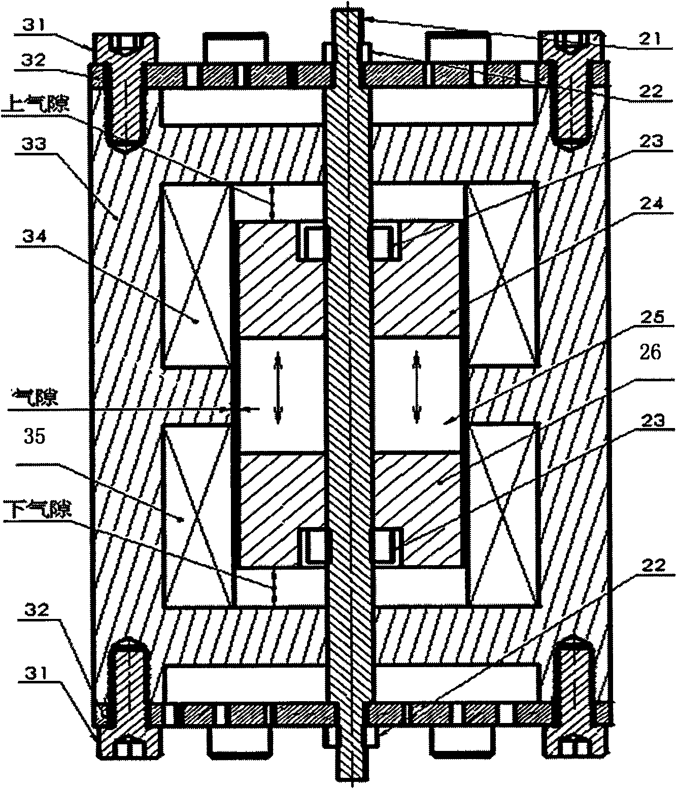
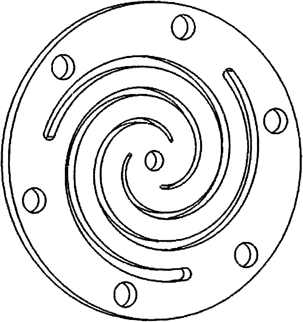
[0014] Figure 1 to Figure 3 It is a structural schematic diagram of an embodiment of a permanent magnet linear reciprocating mechanism of the present invention, Figure 4 yes figure 1 The thrust characteristic curve of embodiment, the reference sign wherein is:

[0015] Mover 20, stator 30, moving rod 21, outer nut 22, inner nut 23, upper moving iron core 24, permanent magnet 25, lower moving iron core 26, bolt 31, leaf spring 32, yoke 33, upper coil 34, lower coil 35.

[0016] The permanent magnet linear reciprocating mechanism in this embodiment is composed of a mover 20 and a stator 30 , the stator 30 is sleeved on the mover 20 , and the mover 20 can reciprocate linearly relative to the stator 30 in the axial direction. Wherein, the stator 30 includes a yoke 33, an upper coil 34 and a lower coil 35, the upper coil 34 and the lower coil 35 are co...


PUM


Abstract

The invention discloses a permanent magnet linear reciprocating mechanism. In the mechanism, when opposite stators are linearly reciprocated, the end positions of motion trails are kept unchanged by adopting a fixed motion channel. On the other hand, an electromagnetic thrust much stronger than a permanent magnetic force can be generated only by applying short-time positive and negative heavy currents to an upper coil and a lower coil at a proper time. Therefore, the mechanism is the strong-trust permanent magnet linear reciprocating mechanism applied to a short stroke. In addition, the mechanism has a simple and feasible structure and high reliability of the system. As a preference, the mechanism adopts an elastic part to support a rotor, thus realizing abrasion-free reciprocating linear motion, further prolonging the service life of the system and improving the reliability of the system.

Description

technical field [0001] The invention relates to the technical field of reciprocating motion mechanisms, in particular to a permanent magnet linear reciprocating motion mechanism. Background technique [0002] Linear reciprocating motion mechanisms are widely used in industrial automation equipment such as compressors, engines, and various fluid pumps. The linear reciprocating motion mechanism generally uses a rotating motor plus a screw or a crank connecting rod to convert the rotating motion of the rotating motor into a linear motion. However, this working method not only has low energy conversion efficiency, but also has a complex mechanism and many parts. The failure rate is high. Using a linear motor can directly produce linear reciprocating motion, but multiple sets of coils are required to generate a traveling wave magnetic field. For fast linear reciprocating motion with a small stroke, the drive control device is complicated and does not have the function of maintai...

Claims


Application Information

Patent Timeline
IPC IPC(8): H02K33/18
Inventor 黄彬彬张杰周杰杨炯廖有用
Owner NINGBO INST OF MATERIALS TECH & ENG CHINESE ACADEMY OF SCI
Features
  • Generate Ideas
  • Intellectual Property
  • Life Sciences
  • Materials
  • Tech Scout
  • Unparalleled Data Quality
  • Higher Quality Content
  • 60% Fewer Hallucinations
Learn More