Hydraulic circuit for construction machine

A technology of hydraulic circuits and construction machinery, applied in construction, machinery equipment, servo meter circuits, etc., to achieve the effect of reducing temperature rise, reducing operating noise, and low noise

Active Publication Date: 2011-01-12
NABLESCO CORP
View PDF8 Cites 18 Cited by
  • Summary
  • Abstract
  • Description
  • Claims
  • Application Information

AI Technical Summary

Problems solved by technology

[0003] However, in a hydraulic circuit of a construction machine using a diverter-type variable displacement piston pump (one-cylinder, two-port discharge diverter pump) having only one swash plate, this cannot be performed optimally since the pump has only one swash plate. negative control

Method used


Image

  • Hydraulic circuit for construction machine
  • Hydraulic circuit for construction machine
  • Hydraulic circuit for construction machine

Examples


no. 1 approach

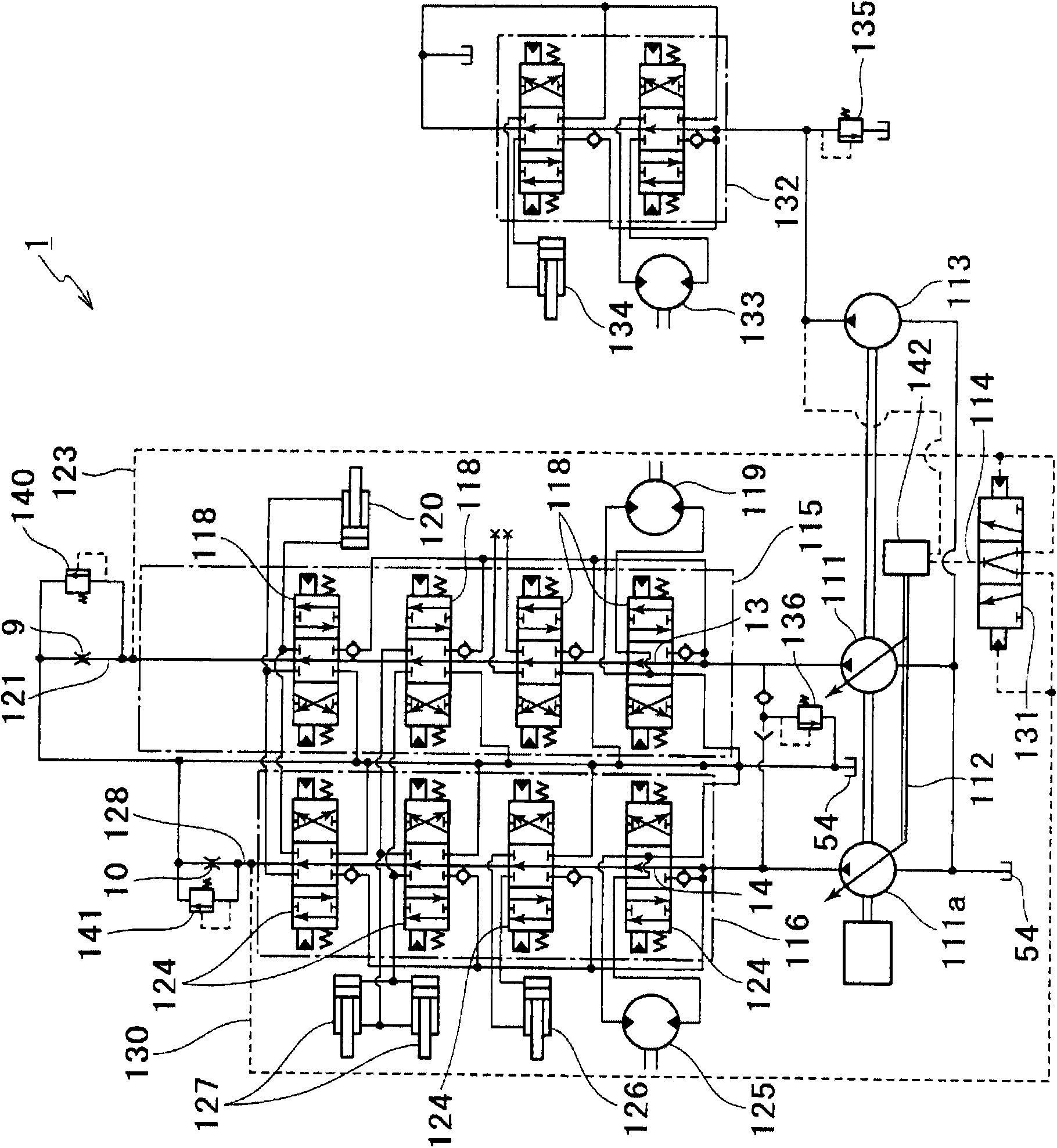
[0095] figure 1 It is a circuit diagram showing the hydraulic circuit of the construction machine according to the first embodiment of the present invention. Here, the pump 111 is a split-flow variable displacement piston pump (shunt pump) in which an even number of pistons are fitted to a hydraulic cylinder base formed by combining an input shaft and a spline, and discharge equal volume of liquid, and has a swash plate 112, and the pump 111 also has a constant torque control mechanism 142 for efficient use of engine power. The constant torque control mechanism 142 is widely used in construction machinery, especially small excavators, etc., and the constant torque control mechanism 142 changes according to the sum of a plurality of discharge pressures, and further according to the discharge pressure of the attached constant discharge displacement pump 113. The angle of the swash plate 112 is used to control the shaft input torque of the pump so that it does not exceed a certa...

no. 2 approach

[0105] Image 6 It is a circuit diagram showing the hydraulic circuit 201 of the second embodiment of the present invention. like Image 6 As shown, the hydraulic excavator using the hydraulic circuit 201 includes: a shunt pump 51 with a regulator 52 for controlling the discharge flow of pressure oil (discharge capacity of the shunt pump); a pilot pump 53; a left hydraulic motor 55 for movement (left moving motor 55); boom frame hydraulic cylinder 56; bucket hydraulic cylinder 57; arm hydraulic cylinder 58; rotation hydraulic motor 59; mobile right side hydraulic motor 60 (right moving motor 60 ); and fuel tank 54. And hydraulic drive mechanisms such as these hydraulic motors ( 55 , 59 , 60 ) and hydraulic cylinders ( 56 to 58 ), pumps ( 51 , 53 ), and regulator 52 are combined into a hydraulic circuit 201 .

[0106] The splitter pump 51 is a variable-capacity one-cylinder, two-port discharge pump, and discharges pressure oil of the same flow rate from the two discharge por...

no. 3 approach

[0136] Figure 7 It is a circuit diagram showing the hydraulic circuit 202 of the third embodiment of the present invention. The present embodiment will be described focusing on the differences between the present embodiment and the above-mentioned second embodiment. In addition, the same reference numerals are used for the same components as those of the second embodiment (the other embodiments are also used in the same way).

[0137] Pressure relief flow control valve

[0138] The main difference between the third embodiment and the second embodiment is that the hydraulic circuit 202 of the third embodiment has pressure relief flow control valves 4 , 5 . like Figure 7 As shown, the hydraulic circuit 202 has a first pressure relief flow control valve 4, and the first pressure relief flow control valve 4 is arranged in the downstream passage 72 of the first pressure relief valve 2 between the first pressure relief valve 2 and the oil tank 54 superior. The first pressur...


PUM


Abstract

Negative control of a split pump having a single swash plate consumes less energy than conventional negative control. A hydraulic circuit (1) for a construction machine is adapted for control of a split pump (111) the discharge volume of which can be reduced according to the magnitude of an external signal pressure. The hydraulic circuit (1) is provided with switching valves (118, 124) for controlling actuators (119, 120, 125, 126, 127), and also with control valves (115, 116) which can feedback, as external signal pressures, back pressures caused by the center bypass flow rates of two systems to the split pump (111). Further, the hydraulic circuit (1) is constructed such that, of the external signal pressures, a minimum pressure (external signal pressure (114)) selected by a low-pressureselecting valve (131) is fed back to the split pump (111).

Description

technical field [0001] The invention relates to a hydraulic circuit of a construction machine adopting a variable-capacity one-cylinder two-port discharge split flow pump. In particular, it relates to hydraulic circuits suitable for small construction machines such as small excavators. Background technique [0002] In the past, the back pressure generated by the size of the bypass flow of the control valve was widely used to negatively control multiple variable capacity piston pumps. Since the multiple pumps each have a swash plate, they can The capacity of the pumps is individually controlled, so that only the required flow rate can be discharged by optimally controlling the swash plate of each pump according to the consumption state of the working oil discharged from each pump (for example, refer to Patent Document 1: Japanese Patent Laid-Open Publication No. Kaiping 5-132977). [0003] However, in a hydraulic circuit of a construction machine using a diverter-type varia...

Claims


Application Information

Patent Timeline
Patent Type & Authority Applications(China)
IPC IPC(8): F15B11/00E02F9/22
CPCE02F9/2285F15B2211/7058F15B2211/30505F15B2211/3127E02F9/2296F15B11/0423F15B2211/5151F15B2211/20553E02F9/2232F15B2211/605F15B2211/20576F15B2211/30515F15B2211/3056F15B2211/46E02F9/2225F15B2211/7053F15B2211/75E02F9/2292F15B2211/7741F15B2211/55F15B2211/50518F15B2211/30535F15B2211/5156F15B2211/40507F15B2211/6051F15B2211/7128F15B2211/329F15B2211/3111F15B2211/71F15B2211/3116E02F9/2239F15B2211/6355
Inventor 池生慎一濑川均
Owner NABLESCO CORP
Why Eureka
Try Eureka