Low-grade heat energy auxiliary-drive composite low-temperature refrigerating system

A low-temperature refrigeration system and auxiliary drive technology, used in refrigerators, refrigeration and liquefaction, lighting and heating equipment, etc. problem, to achieve the effect of significant energy saving, power consumption reduction and power saving effect

Inactive Publication Date: 2011-01-19
HENAN UNIV OF SCI & TECH
View PDF6 Cites 22 Cited by
  • Summary
  • Abstract
  • Description
  • Claims
  • Application Information

AI Technical Summary

Problems solved by technology

[0002] Ejection refrigeration has the advantages of using renewable energy such as solar energy, geothermal energy, and industrial waste heat to achieve refrigeration. However, because the system uses a single-component refrigerant and the compression ratio of the ejector is relatively small, it is difficult to achieve the cooling medium of the condenser. When the cooling temperature is high, the required condensation pressure is required, so the cooling temperature is high, and the efficiency of the system is low, which greatly limits its practical application
Therefore, low-temperature refrigeration usually adopts cascade refrigeration cycle and self-cascade refrigeration cycle. Although these two cycles can obtain refrigeration temperatures in the range of -50°C~-120°C, they are driven by high-grade electric energy, and , as the cooling temperature drops, the cooling efficiency drops, and the power consumption of the compressor increases. It can be seen that neither the cascade refrigeration cycle nor the self-cascade refrigeration cycle has significant advantages in energy saving and emission reduction.

Method used


Image

  • Low-grade heat energy auxiliary-drive composite low-temperature refrigerating system
  • Low-grade heat energy auxiliary-drive composite low-temperature refrigerating system
  • Low-grade heat energy auxiliary-drive composite low-temperature refrigerating system

Examples


Embodiment Construction

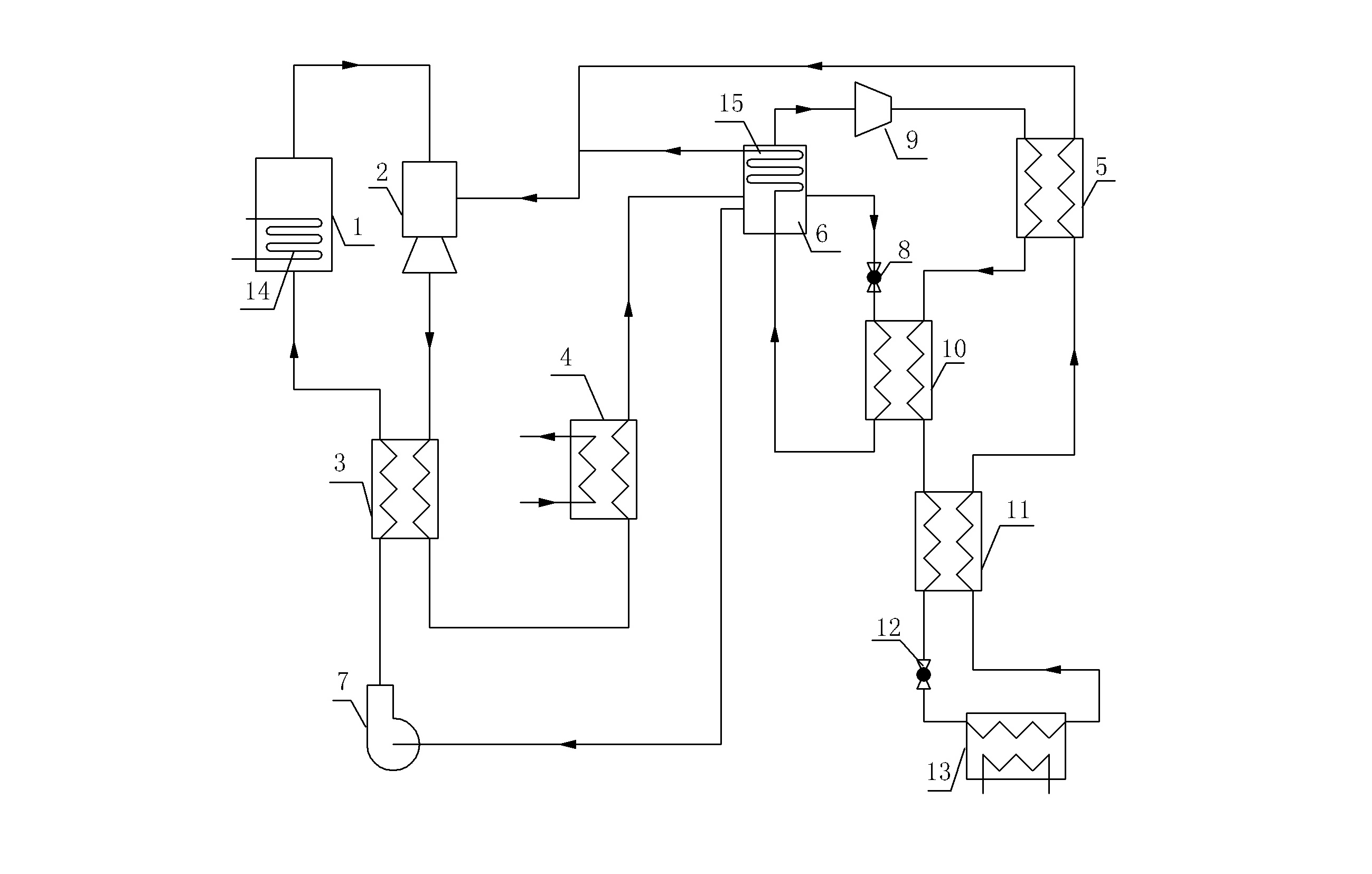
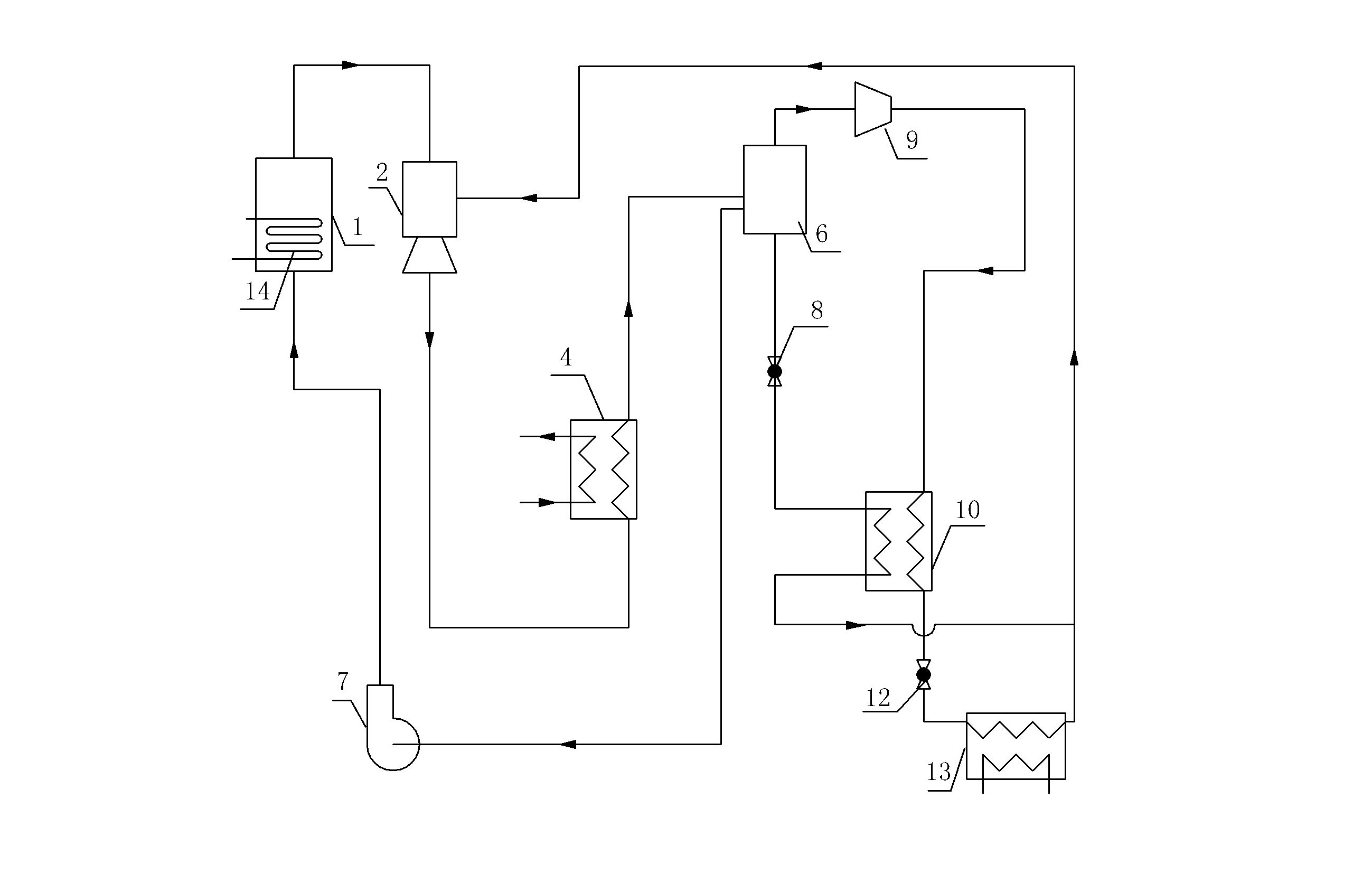
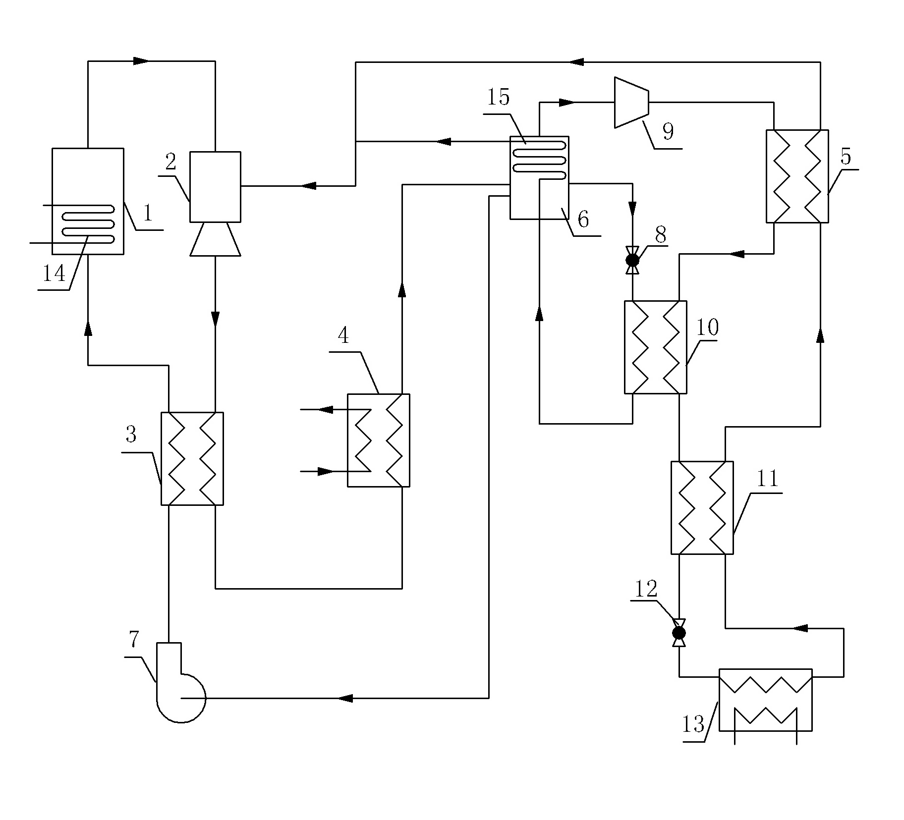
[0013] Such as figure 1 Shown, the embodiment 1 of the composite low-temperature refrigeration system driven by low-grade thermal energy auxiliary drive of the present invention, figure 1 The arrows in indicate the direction of fluid flow in the piping connecting the various parts of the system. The system includes a compression refrigeration part and a low-grade thermal energy auxiliary part. In an embodiment of the system, a binary non-azeotropic mixed refrigerant refrigerant composed of a mixture of a high-boiling point refrigerant and a low-boiling point refrigerant is used. The high-boiling point refrigerant It is one of R600a, R152a, R134a or R22, and the low boiling point working substance is one of R23, R170, R290 or R32.

[0014] The compression refrigeration part is similar to the prior art, including a compressor 9, a second regenerator 5, a high-temperature side channel of a condensation evaporator 10, a third regenerator 11, a second throttling component 12, and ...


PUM


Abstract

The invention discloses a low-grade heat energy auxiliary-drive composite low-temperature refrigerating system. The system comprises a generator, an ejector, a working medium pump, a condenser, a gas-liquid separator, a compressor, a first throttling component, a condensation evaporator, a second throttling component, an evaporator and a heater. A high-boiling-point component is condensed into liquid to serve as a low-boiling-point component cooling medium through the ejector driven by the low-grade heat energy; and the ejector has another function of increasing suction pressure of the low-boiling-point component at a suction port of the compressor to reduce the compression ratio of the compressor so as to realize lower refrigerating temperature. Because the compression process of the high-boiling-point component during circulation is finished by the ejector, the power consumption of the compressor is reduced; and the ejector also improves the suction pressure of the low-boiling-point component at the suction port of the compressor and is also favorable for further reducing the power consumption of the compressor. The system has the advantages of realizing high-efficiency utilization of a low-grade energy source, along with stable running, obvious energy saving effect and broad application prospect.

Description

technical field [0001] The invention relates to a refrigeration system, in particular to a composite low-temperature refrigeration system in which a compressor and an ejector work together. Background technique [0002] Ejection refrigeration has the advantages of using renewable energy such as solar energy, geothermal energy, and industrial waste heat to achieve refrigeration. However, because the system uses a single-component refrigerant and the compression ratio of the ejector is relatively small, it is difficult to achieve the cooling medium of the condenser. When the cooling temperature is high, the required condensation pressure is required, so the cooling temperature is high, and the efficiency of the system is low, which greatly limits its practical application. Therefore, low-temperature refrigeration usually adopts cascade refrigeration cycle and self-cascade refrigeration cycle. Although these two cycles can obtain refrigeration temperatures in the range of -50°C...

Claims


Application Information

Patent Timeline
Patent Type & Authority Applications(China)
IPC IPC(8): F25B27/00F25B25/00
Inventor 王林谈莹莹王志远闫晓娜梁坤峰崔晓龙王雨马爱华
Owner HENAN UNIV OF SCI & TECH
Why Eureka
Try Eureka