Dynamic image modulation transfer function measuring device

A modulation transfer function and measurement device technology, applied in the field of moving image modulation transfer function measurement devices, can solve the problems of moving image modulation transfer function measurement error, complex mechanical structure, and no consideration of image vignetting, etc., to achieve image elimination Vignetting, an effect that improves accuracy

Active Publication Date: 2011-01-19
HARBIN INST OF TECH
View PDF6 Cites 49 Cited by
  • Summary
  • Abstract
  • Description
  • Claims
  • Application Information

AI Technical Summary

Problems solved by technology

Its shortcomings are: ①This experimental device can only measure the modulation transfer function of low-frequency simple harmonic motion moving images and cannot take into account other motion forms; To measure at a specific spatial frequency, if you want to draw the moving image modulation transfer function curve, you need to replace the discrimination rate board with different spatial frequencies for multiple measurements, and there are many measurement steps; in order to reduce the measurement steps, you can use the grating disc to move along the vertical optical axis However, due to the introduction of a structure that moves the grating disk in the direction perpendicular to the optical axis, and it must be matched with the image acquisition end to perform measurement, the mechanical structure of the entire device is much more complicated.
However, its disadvantages are: ① It does not take into account that the movement of the target will cause image vignetting, so that the measurement results of the moving image modulation transfer function are mixed with the influence of vignetting, resulting in errors in the measurement results of the moving image modulation transfer function; ② the device lacks a A method that can detect whether the measurement result is correct in real time, making it impossible to know whether the measurement result is correct or not

Method used


Image

  • Dynamic image modulation transfer function measuring device
  • Dynamic image modulation transfer function measuring device
  • Dynamic image modulation transfer function measuring device

Examples


Embodiment 1

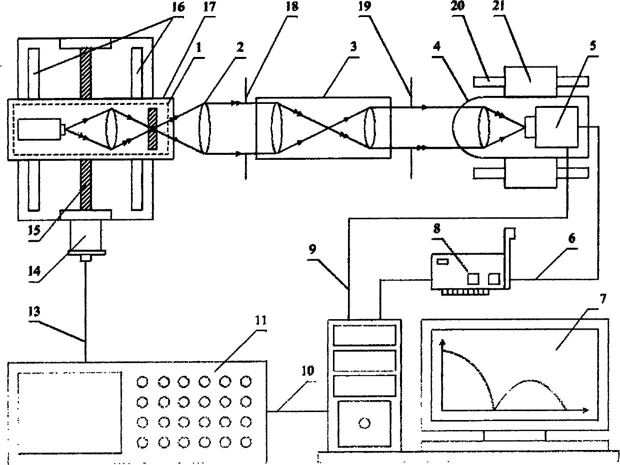
[0033] figure 2 It is a schematic structural diagram of a moving image modulation transfer function measurement device for external triggering and synchronous exposure, including a point light source 1, a collimating objective lens 2, and a pupil formed by a red laser with a power of 20 mW and a pinhole with a diameter of 15 μm arranged in sequence along the light propagation direction Coupling system 3, photoelectric imaging system 4, also comprise stepper motor driver 11, 42BYG250 type stepper motor motor 14, leading screw 15, computer 7 and OK_M10B type image acquisition card 8; Wherein, computer 7 controls driver by driver control line 10 11; the driver 11 drives the motor 14 to drive the lead screw 15 to rotate through the motor drive control line 13, so that the slider 17 carrying the point light source 1 moves along the guide rail 16 in the direction perpendicular to the optical axis according to the prescribed trajectory motion equation; the photoelectric imaging syste...

Embodiment 2

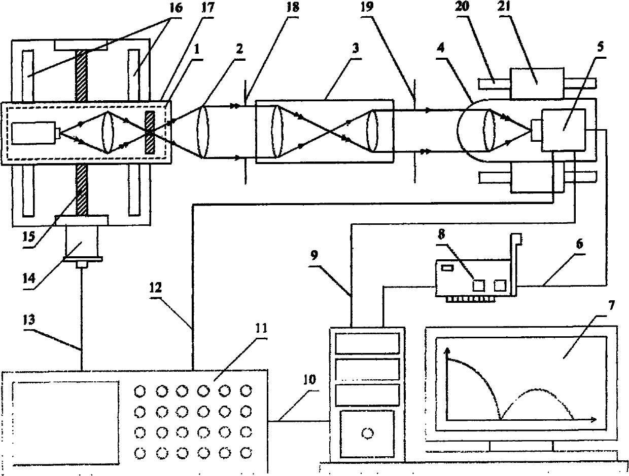
[0036] image 3 It is a structural diagram of a moving image modulation transfer function measurement device with software synchronous exposure, including a point light source 1, a collimating objective lens 2, and a pupil coupling that are sequentially configured along the direction of light propagation with a red laser with a power of 20 mW and a pinhole with a diameter of 15 μm. System 3, photoelectric imaging system 4, also includes stepper motor driver 11, 42BYG250 type stepper motor motor 14, leading screw 15, computer 7 and OK_M10B type image acquisition card 8; Wherein, computer 7 controls driver 11 by driver control line 10 The driver 11 drives the motor 14 to drive the lead screw 15 to rotate through the motor drive control line 13, so that the slide block 17 carrying the point light source 1 moves along the guide rail 16 according to the prescribed trajectory motion equation to move in the direction of the vertical optical axis; the photoelectric imaging system 4 is ...


PUM


Abstract

The invention relates to a dynamic image modulation transfer function measuring device belonging to the field of optical property tests and sequentially comprising a point light source, a collimator objective, a pupil coupling system and a photoelectronic imaging system along the light propagating direction, and also comprising a driver, a motor, a lead screw, a computer and an image collector card, wherein the pupil coupling system adopts parallel light incidence and parallel light emergence; the entrance pupil of the pupil coupling system and the exit pupil of the collimator objective have same size and same position; the exit pupil of the pupil coupling system and the entrance pupil of the photoelectronic imaging system have same size and same position; the pupil coupling system is dismantled, and the exit pupil of the collimator objector and the entrance pupil of the photoelectronic imaging system have same size and same position; and the time difference of image acquisition of the photoelectronic imaging system and the travel of a sliding block I is set by a hardware delay circuit or software delay program. The device can not only eliminate image vignetting caused by target travel, but also can realize time comparison of the measurement result and the theoretical model.

Description

technical field [0001] The invention relates to a measuring device for a moving image modulation transfer function in the field of optical property testing. Background technique [0002] The concept of the transfer function is the ratio of the Laplace transform of the linear system response (ie output) quantity to the Laplace transform of the excitation (ie input) quantity under zero initial conditions. The transfer function was first applied in the classical control theory, and the frequency response method and the root locus method are the main research methods developed on the basis of the transfer function. With the in-depth research on the concept of transfer function and its scope of application, the transfer function method has been widely used in various scientific and engineering fields, as long as the research object is the relationship between the excitation and response of the system, and the system is not linear in the time domain. change or satisfy the propert...

Claims


Application Information

Patent Timeline
Patent Type & Authority Applications(China)
IPC IPC(8): G01M11/02
Inventor 丁雪梅赵烟桥刘俭谭久彬
Owner HARBIN INST OF TECH
Why Eureka
Try Eureka