Direct current offset probe card for radio frequency test

A technology of DC bias and radio frequency testing, which is applied in the direction of measuring devices, electronic circuit testing, measuring electricity, etc., can solve the problems that cannot meet the requirements of radio frequency on-chip testing, the substrate circuit does not have a shockproof circuit, and the substrate size is large, etc., to achieve improvement The effect of testing quality, eliminating noise and vibration, and reducing mutual interference

Active Publication Date: 2011-01-19
南京国博电子股份有限公司
View PDF5 Cites 13 Cited by
  • Summary
  • Abstract
  • Description
  • Claims
  • Application Information

AI Technical Summary

Problems solved by technology

At present, the probe card substrate provided by the probe card manufacturer is mainly used for DC on-wafer testing. The size of the substrate is too large to meet the requirements of RF on-wafer testing. In addition, the substrate circuit does not have a special anti-shock

Method used


Image

  • Direct current offset probe card for radio frequency test
  • Direct current offset probe card for radio frequency test
  • Direct current offset probe card for radio frequency test

Examples


Embodiment Construction

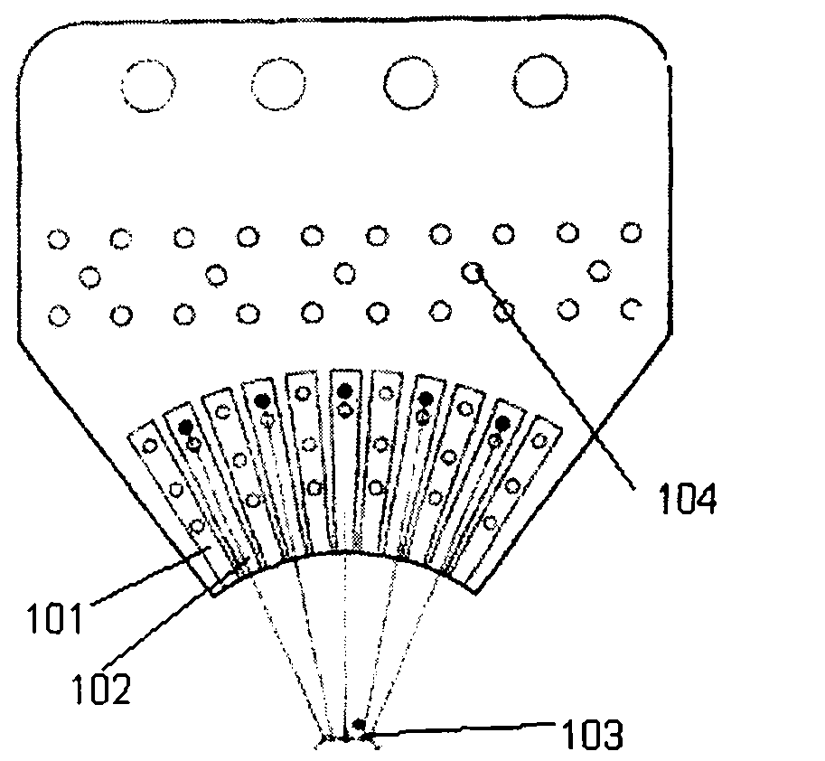
[0011] Control attached figure 1 , its structure is to include a fan-shaped probe card substrate, a plurality of signal lines 102 and grounding lines 101 are arranged on the probe card substrate, at least one grounding line 101 is arranged on the distance between the signal lines 102 and the signal lines 102, there is Electrical protection to prevent external noise from interfering with the signal line. The connector installation position 104 is the leading end of the signal line 102 and is used for connecting the bias signal of the test equipment. One end of the signal line 102 is connected to the connector installation location 104 , and the other end of the signal line 102 is connected to a probe. The back side of the signal line 102 is provided with an anti-vibration circuit.

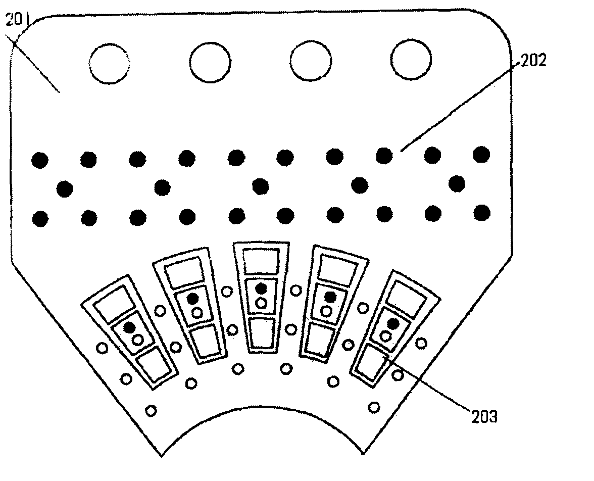
[0012] Control attached figure 2 , its structure is to include a large-area metal ground 201, the joint installation position 202 communicates with it at the back of 104, and the reserved anti-s...


PUM


Abstract

The invention provides a direct current offset probe card for radio frequency test. The direct current offset probe card is characterized by comprising a sectorial probe card base plate, wherein a plurality of signal circuits and grounding circuits are arranged on the probe card base plate; at least one grounding circuit is arranged in a space between the signal circuits and conducts an electrical protection function of effectively avoiding the interference of external noise with the signal circuit; a connector is arranged at leading-out terminal of the signal circuit for connecting offset signals of test equipment; one end of the signal circuit is connected with the mounting position of the connector, and the other end of the signal circuit is connected with a probe; and the back of the signal circuit is provided with a shockproof circuit. The direct current offset probe card has the advantages that: the signal circuits transmit the offset signals of the test equipment, and the grounding circuits are electrically connected to the electric potential zero point of a tester and serves as the reference data of characteristic impedance of each signal circuit; and different capacitors and resisters are arranged according to different tested devices so as to reduce the interferences between signals. The direct current offset probe card is simple in structure design and is suitable for standard production. The direct current offset probe card can reduce signal noise and circuit oscillation and improve the on-line testing quality of radio frequency.

Description

technical field [0001] The invention relates to a special-shaped DC bias probe card with anti-shock circuit design for radio frequency testing, which belongs to the field of integrated circuit design technology. Background technique [0002] The probe card is to directly contact the probe on the probe card with the chip test pad on the radio frequency integrated circuit chip, cooperate with the test equipment and software control to transmit the test signal through the circuit board on the probe card to the probe and even the chip. To achieve the purpose of automated chip-level testing, the arrangement density of the probes needs to be fine enough to correspond to the gap between adjacent test pads on the chip, and a single probe card can be widely used in integrated circuit chips with different manufacturing technologies. The circuit board design of the needle card often does not use the specific wiring layout as the circuit transmission structure, but sets the jumper struc...

Claims


Application Information

Patent Timeline
IPC IPC(8): G01R1/067G01R31/28
Inventor 吴振海徐光钱峰
Owner 南京国博电子股份有限公司
Why Eureka
Try Eureka