Permanent-magnetic suspension supporting cylindrical linear motor

A linear motor, cylindrical technology, applied in electrical components, electromechanical devices, electric components, etc., can solve the problems of low motion accuracy and dynamic response ability, lubricating fluid pollution, etc., and achieve the effect of improving motion accuracy and dynamic response ability.

Inactive Publication Date: 2011-01-19
CENT SOUTH UNIV
View PDF4 Cites 16 Cited by
  • Summary
  • Abstract
  • Description
  • Claims
  • Application Information

AI Technical Summary

Problems solved by technology

The wear, low-speed crawling, and lubricant pollution caused by mechanical friction in mechanical linear b

Method used


Image

  • Permanent-magnetic suspension supporting cylindrical linear motor
  • Permanent-magnetic suspension supporting cylindrical linear motor

Examples


Embodiment Construction

[0015] The present invention will be further described below in conjunction with the accompanying drawings and specific embodiments.

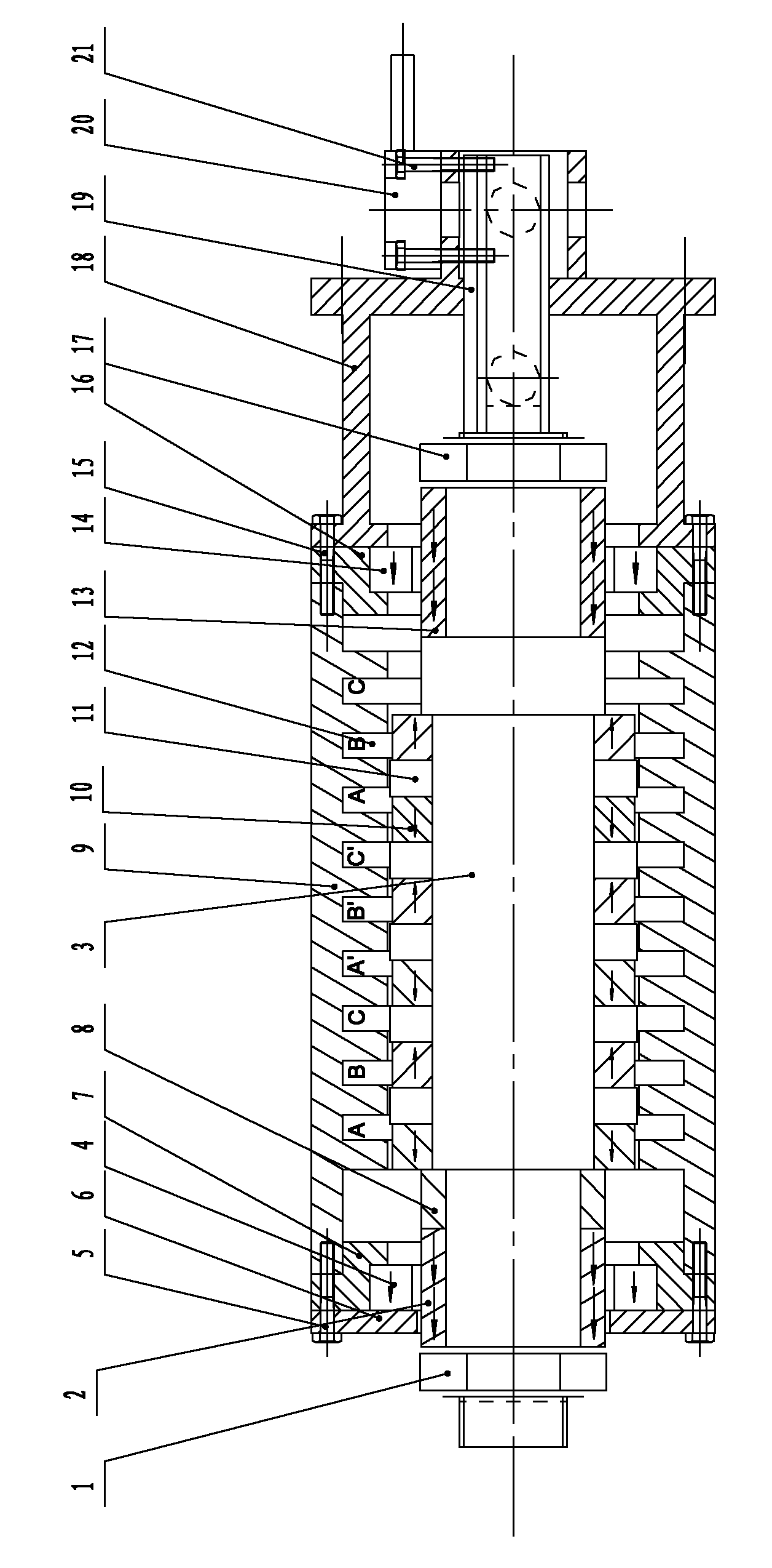
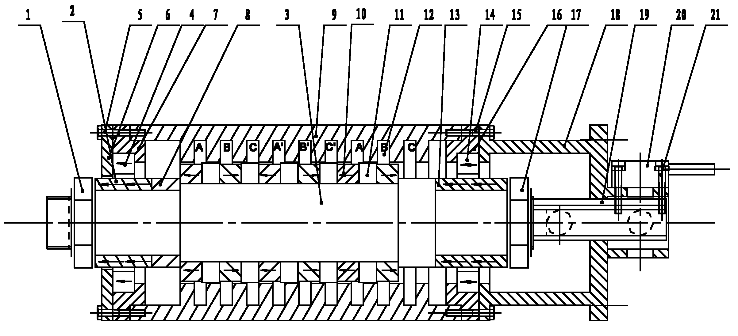
[0016] see figure 1 , the linear motor stator core 9 is provided with a linear motor long stator coil winding 12, the motor mover main shaft 3 is provided with an annular permanent magnet array 10 and a magnetic isolation ring 11, the linear motor stator core 9 and the motor mover The main shaft 3 adopts a long stator and short mover structure. The left end of the linear motor stator core 9 is provided with a left inner support seat 7 and a left outer pressure plate 6 through a right fastening screw 15, and the right end is provided with a right inner support through a right fastening screw 15. The seat 16 and the right outer pressure plate 18 are provided with the left end magnetic bearing stator permanent magnet ring 4 in the left inner support seat 7, and the left end of the motor mover main shaft 3 is provided with the left end magnetic bea...


PUM


Abstract

The invention discloses a permanent-magnetic suspension supporting cylindrical linear motor. The linear motor comprises a permanent-magnetic bearing stator permanent-magnetic ring, a mover permanent-magnetic ring, a cylindrical linear motor stator and mover permanent-magnetic ring array, a linear displacement sensor, fastening screws and a corresponding linear motor drive system. A linear motor mover is supported by adopting a passive axial permanent-magnetic bearing, and no mechanical contact between the mover and a stator is produced by means of automatic centering and repulsion action of a radial permanent-magnetic bearing, so friction (theoretically no friction is produced) is reduced, lubricating oil is not needed, an active control coil is not needed, and heat is not produced; and compared with a motor supported by a mechanical bearing, the linear motor has better dynamic performance, easy maintenance and long service life. Once the passive magnetic bearing is designed and sized, the rigidity of the magnetic bearing is determined and changed along with the moving distance and is lower than that of an active bearing, and the precision is limited.

Description

technical field [0001] The invention relates to a motor, in particular to a cylindrical linear motor supported by permanent magnetic suspension. technical background [0002] In some microelectronics manufacturing and bio-manufacturing fields, high requirements are placed on the thermal changes of equipment movement and the cleanliness of operations. The wear, low-speed crawling and lubricating fluid pollution caused by mechanical friction in mechanical linear bearings have adverse effects, and the motion accuracy and dynamic response capability of the system are low. Contents of the invention [0003] The technical problem to be solved by the present invention is to provide a permanent magnetic levitation supported cylindrical linear motor that can realize non-contact maglev linear motion and can effectively improve the motion accuracy and dynamic response capability of the system. [0004] In order to solve the above-mentioned technical problems, the permanent magnetic ...

Claims


Application Information

Patent Timeline
IPC IPC(8): H02K41/02
Inventor 李群明邓华韩雷周英
Owner CENT SOUTH UNIV
Why Eureka
Try Eureka