Remote power supply system for repeater

A technology of remote power supply and repeater, which is applied in the direction of radio relay system, collector, electric vehicle, etc. Problems such as delays in place, to achieve the effect of convenient daily maintenance and management, saving installation costs, and easy management

Inactive Publication Date: 2011-01-19
ALLWIN TELECOMM
View PDF6 Cites 2 Cited by
  • Summary
  • Abstract
  • Description
  • Claims
  • Application Information

AI Technical Summary

Problems solved by technology

[0003] 1. Limited site selection affects the network coverage effect: In the past, the site selection of repeaters was limited by the construction of the power supply system. Device coverage
[0004] 2. The opening of the station is not timely: due to the cumbersome approval process of the power system, the opening process of the repeater and other communication equipment has been seriously affected, resulting in some completed repeater systems not being opened due to the delay in the power system
[0005] 3. Unstable power supply voltage: The selection of civilian electricity for communication equipment such as repeaters often cannot guarantee the continuous stability of its voltage. Abnormal fluctuations in the power supply voltage of the equipment will cause failure or even burnout of the internal power supply module of the communication equipment.
[0006]Aiming at the problem that limited site selection affects network coverage, communication operators usually only build more base stations and lay a large number of power supply and communication cables to ensure the quality of their services and Reliability, but the cost of this is huge engineering costs and post-maintenance costs

Method used


Image

  • Remote power supply system for repeater
  • Remote power supply system for repeater
  • Remote power supply system for repeater

Examples


Embodiment Construction

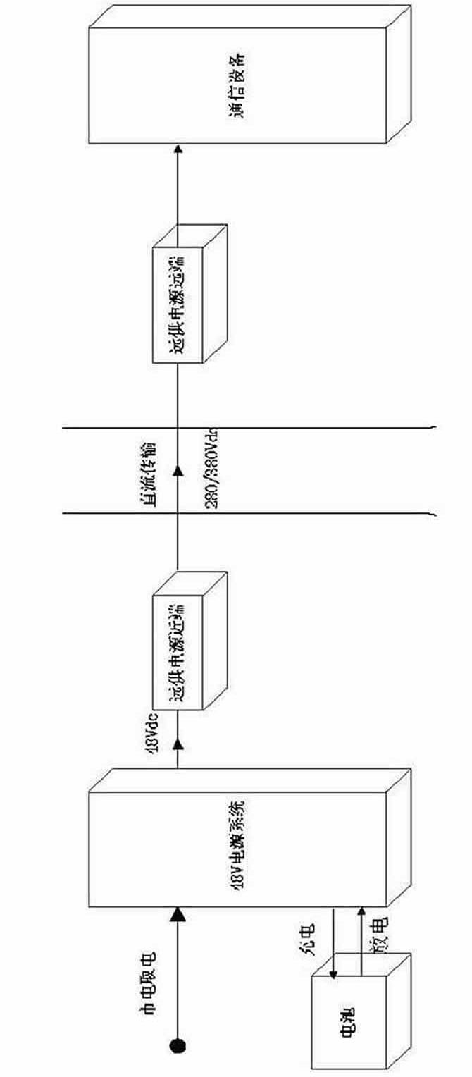
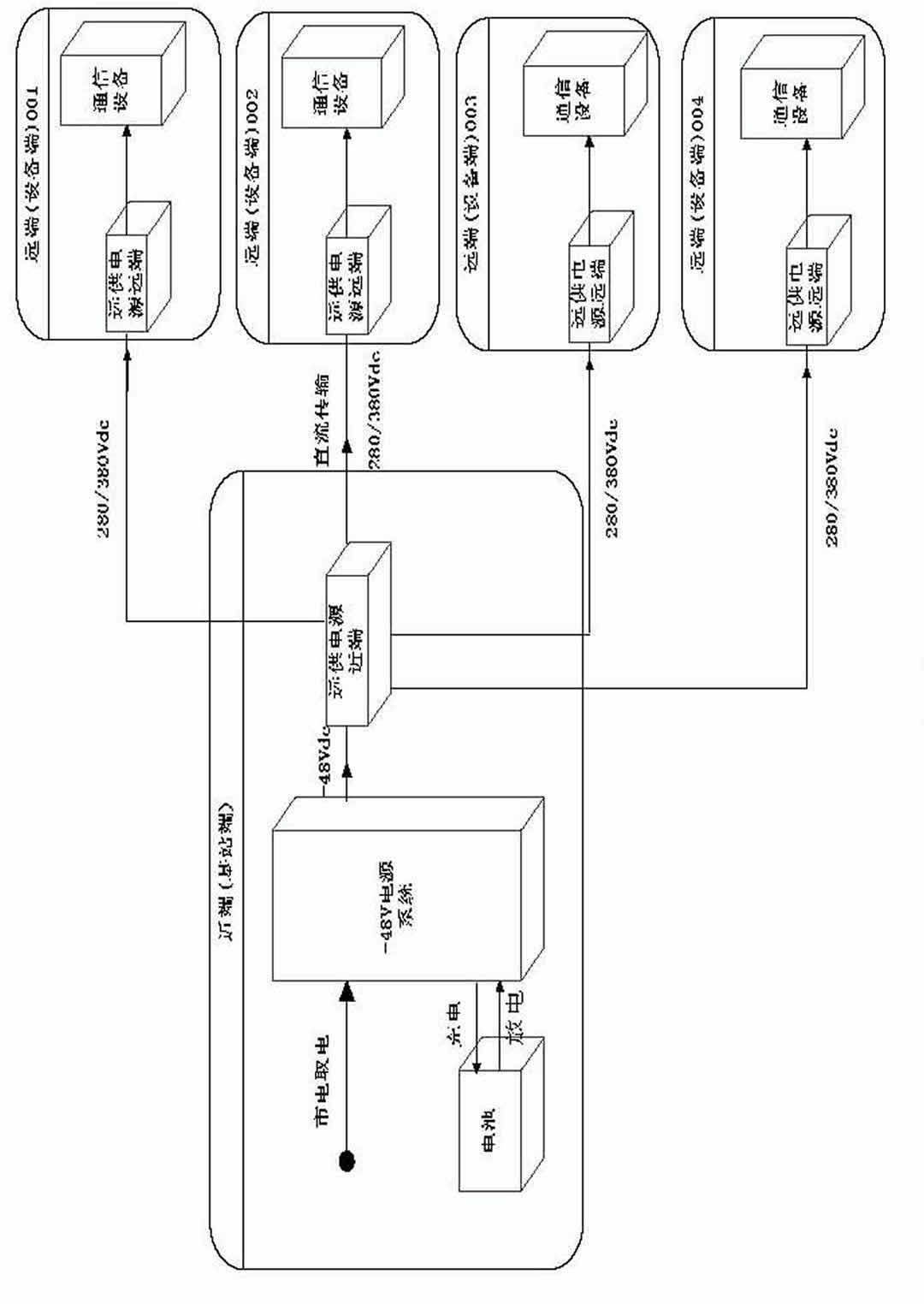
[0025] The remote power supply system consists of local (near-end) and remote equipment. Its working principle is to select -48V direct current from the communication base station computer room, and boost it into a suitable DC high voltage (DC / DC) through the remote power supply local (near-end) equipment. After transformation), it is sent to the remote device of the remote power supply through the composite optical cable, and the remote device of the remote power supply converts the current to an appropriate voltage and then supplies it to remote micro cells, optical transceivers, long-distance dry placement or other indoor distribution. A power supply method for the device.

[0026] As shown in the figure, the repeater remote power supply system includes a near-end part and a far-end part; the near-end part includes a base station DC power supply cabinet and a near-end machine; the remote part includes a remote machine; the base station The transmission port of the DC power ...


PUM


Abstract

The invention belongs to the technical field of mobile communication, and in particular relates to a power supply system for a repeater. The system comprises a near-end part and a far-end part, wherein the near-end part comprises a base station direct-current power supply cabinet and a near-end machine; the far-end part comprises a far-end machine; the transmission port of the base station direct-current power supply cabinet is connected with the transmission port of the near-end machine; and the output end of the near-end machine is connected with the input end of the far-end machine. The near-end part is also provided with a storage battery; the port of the storage battery is connected with the port of the base station direct-current power supply cabinet; the near-end machine comprises a rectifying module and a monitoring module; the port of the rectifying module is connected with the port of the monitoring module; the monitoring module monitors and controls voltage and current of the rectifying module and transmits the voltage and current to a terminal control computer through 485 communication; and the rectifying module is used for adjusting and stabilizing the voltage and current and supplying power to the terminal repeater. The power supply system has the advantages of high safety and reliability, convenient daily maintenance and management, wide environmental adaptation range and high efficiency.

Description

technical field [0001] The invention belongs to the technical field of mobile communication, and in particular relates to a power supply system for a repeater. Background technique [0002] With the increasing improvement of GSM network construction, the coverage of roads, railways and scenic spots has become an urgent requirement for the further development of the network. The optimization of the network has become more and more important, but it is also facing great difficulties. [0003] 1. Limited site selection affects the network coverage effect: In the past, the site selection of repeaters was limited by the construction of the power supply system. The coverage effect of the device. [0004] 2. Late opening of stations: Due to the cumbersome approval process of the power system, the opening process of communication equipment such as repeaters has been seriously affected, and some completed repeater systems have not been opened due to the delay of the power system. ...

Claims


Application Information

Patent Timeline
IPC IPC(8): H04B7/14H02J7/00
Inventor 杜方胡颖李军张笑傲徐勇
Owner ALLWIN TELECOMM
Why Eureka
Try Eureka