Processing method of amorphous alloy stator core slot and locking and positioning clamp thereof

An amorphous alloy, stator core technology, applied in metal processing equipment, metal processing mechanical parts, positioning devices, etc., to achieve the effects of low cost, high efficiency and long processing cycle

Active Publication Date: 2011-01-26
DONGMING MOTOR ELECTRICSHENZHEN CO LTD
View PDF1 Cites 13 Cited by
  • Summary
  • Abstract
  • Description
  • Claims
  • Application Information

AI Technical Summary

Problems solved by technology

The present invention also solves the problem of the locking and positioning fixture required during the processing of the amorphous alloy stator core embedding groove

Method used


Image

  • Processing method of amorphous alloy stator core slot and locking and positioning clamp thereof
  • Processing method of amorphous alloy stator core slot and locking and positioning clamp thereof
  • Processing method of amorphous alloy stator core slot and locking and positioning clamp thereof

Examples


specific Embodiment 1

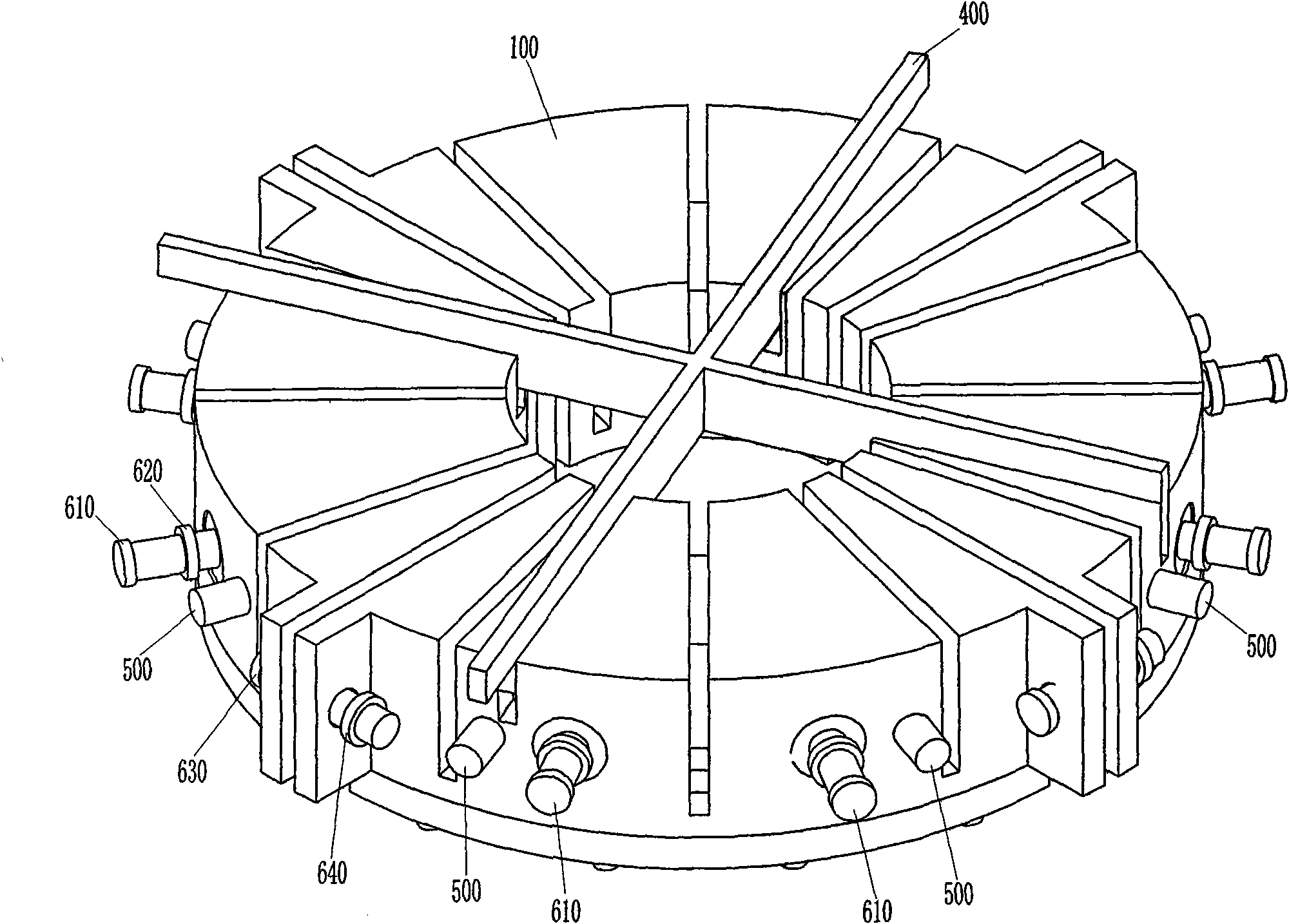
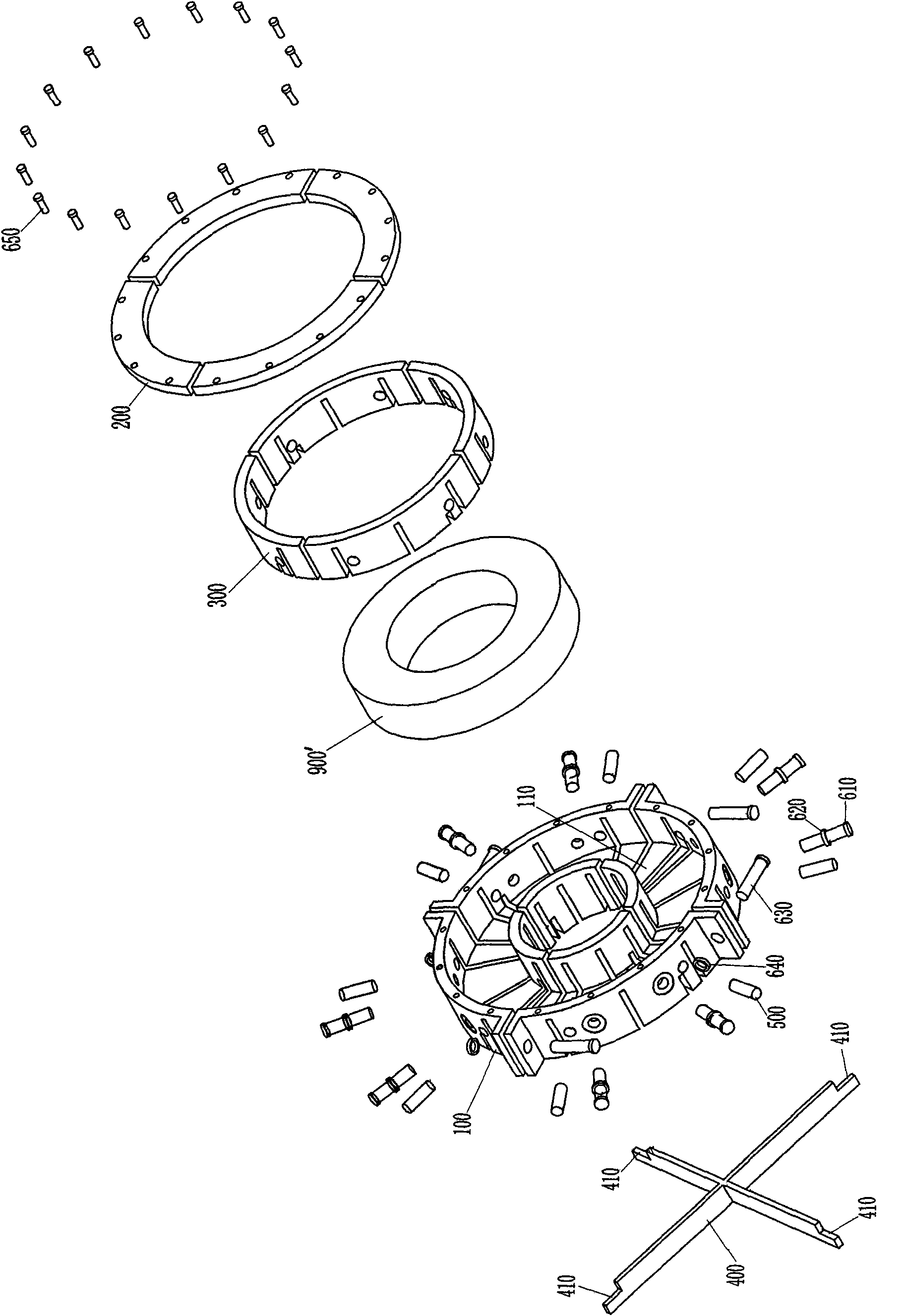
[0078] see Figure 2 to Figure 13 , Figure 22 and Figure 23 , the present invention is used to process the locking and positioning fixture of the amorphous alloy stator core slot, including a housing 100, a bottom plate 200, a moving clamping ring 300, a positioning plate 400, eight clamping bolts 610, and four fixing bolts 630 , four fixing nuts 640, eight positioning pins 500 and sixteen screws 650; the housing 100 is a cylinder 120 provided with a bottom surface 110, and the cylinder is provided with a cylinder body 130 upward from the central part of the bottom surface 110 inner wall, The outer diameter of the cylinder body 130 is adapted to the inner diameter of the stator core 900' to be processed, the cylinder body 130 and the bottom surface 110 are provided with the same central through hole 140, the outer wall of the cylinder body 130, the inner wall of the cylinder 120 and the bottom surface 110 The inner wall forms a cavity 150, and the ring wall of the cylinder...

specific Embodiment 2

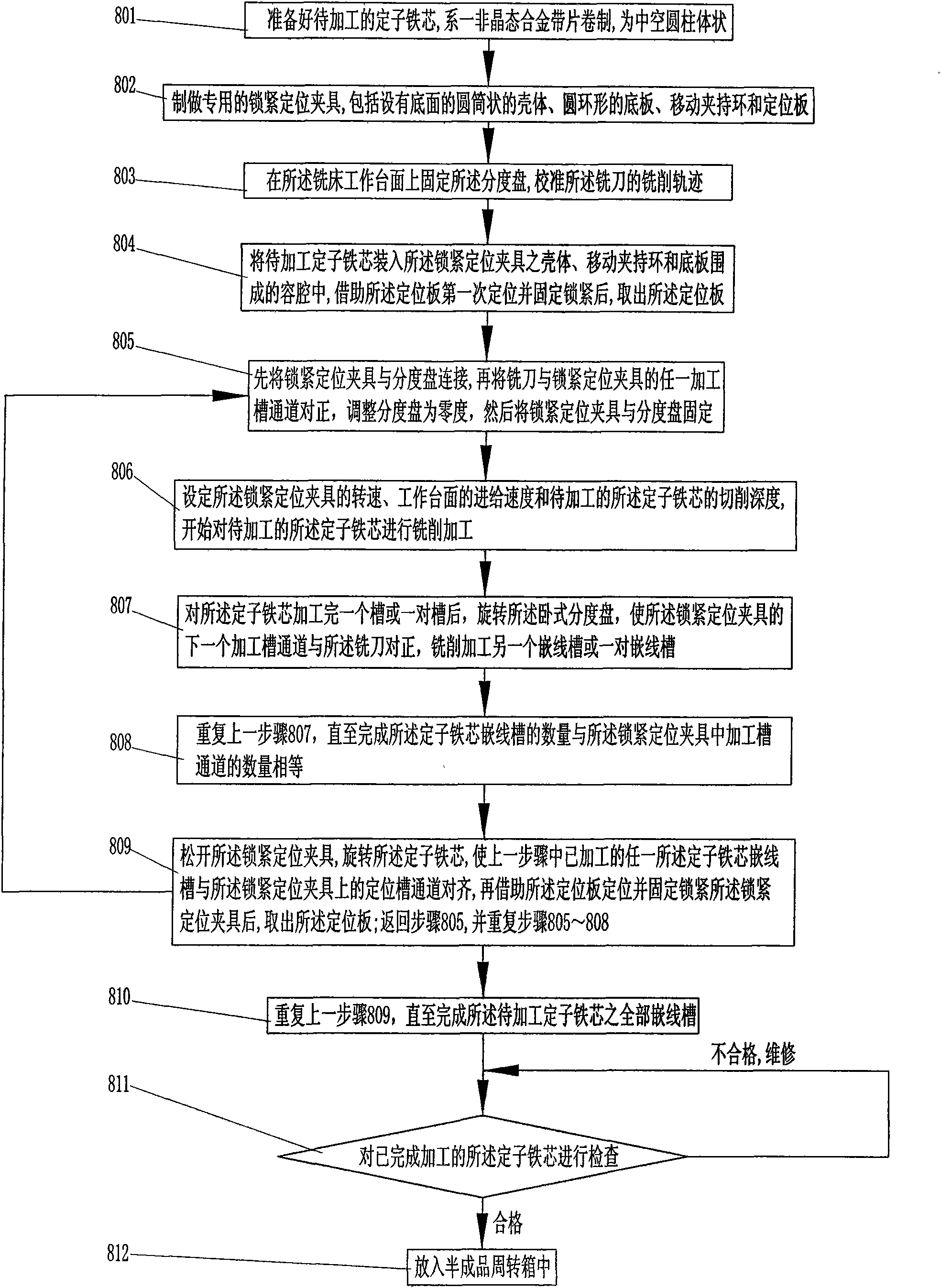
[0083] see Figure 1 to Figure 3 and Figure 14 to Figure 23 , the processing method of the amorphous alloy stator core groove of the present invention adopts milling processing, and the equipment used includes the horizontal milling machine equipment for completing the cutting processing task of the amorphous alloy stator core 900′ to be processed, and completing the stator iron core to be processed. The horizontal indexing plate for rotating and positioning the core 900 ′, the disc milling cutter for radially cutting the stator core 900 ′ to be processed, and the locking and positioning fixture for radially clamping and positioning the stator core 900 ′ The locking and positioning fixture adopts the locking and positioning fixture in the first embodiment. In this embodiment, the width dimension of the processing groove channel 160 of the housing 100 in the locking and positioning fixture, the moving clamp The width dimension of the processing groove passage 360 ​​of the hol...


PUM


Abstract

The invention relates to a processing method of an amorphous alloy stator core slot, which comprises the steps of: making a special locking and positioning clamp used for processing the amorphous alloy stator core slot; packing a stator core to be processed into the locking and positioning clamp for repeatedly positioning and fixedly locking the stator core; and milling a batch of stator core cable embedding trays after each time of positioning and fixedly locking until finishing all the cable embedding trays of the stator core to be processed. The processing method of the invention has the advantages of high efficiency, stable quality, low cost and the like, eliminates the problems of cracking and falling-off of the edge of the amorphous alloy stator core, caused by the impact of cutting force in a traditional mechanical processing method, and also avoids the problem on affecting processing due to nonconductive phenomenon caused by insulation of an adhesive in wire cutting. The invention also relates to the locking and positioning clamp used for processing the amorphous alloy stator core slot.

Description

【Technical field】 [0001] The present invention relates to the components of the magnetic circuit of the motor and its manufacturing method, in particular to the manufacturing method of the stator body of the motor, and in particular to the processing method of the stator core embedding slot made of amorphous alloy material, and the present invention also relates to the Locking and positioning fixture in the process of stator core embedding groove processing. 【Background technique】 [0002] Most of the traditional generators and motors use silicon steel laminations as the stator core. The resistivity and magnetic permeability of silicon steel laminations are low. When the motor runs at high speed, the eddy current is serious, resulting in large iron loss, especially in high frequency motors. Larger, resulting in reduced performance of the motor due to high temperature rise, and shortened motor life; this type of motor generally cannot be used at a high frequency of several ki...

Claims


Application Information

Patent Timeline
Patent Type & Authority Applications(China)
IPC IPC(8): B23C3/28B23Q3/06
Inventor 葛伟石雷谢伟
Owner DONGMING MOTOR ELECTRICSHENZHEN CO LTD
Why Eureka
Try Eureka