
Membrane-electrode electrolytic water tank

A membrane electrode and water tank technology, which is applied in the electrolysis process, electrolysis components, cells, etc., can solve the problems of high water resistance, prone to leakage accidents, and application of large voltage, and achieve the effect of high safety.

Inactive Publication Date: 2011-01-26
褚礼政
View PDF0 Cites 0 Cited by
  • Summary
  • Abstract
  • Description
  • Claims
  • Application Information

AI Technical Summary

Problems solved by technology

[0002] At present, in the field of chemical industry, in order to produce hydrogen and oxygen, electrolysis of water is often used. In this process, an electrolyzer is used. The working principle of an ordinary electrolyzer is as follows. Two opposite electrode plates are set in the water tank. , set a gas diaphragm between the plates, and then directly energize the water tank, so that the positively charged hydrogen ions move to the cathode plate, and the negatively charged hydroxide ions move to the anode plate, and oxidize at the cathode and anode plates respectively The reduction reaction generates hydrogen and oxygen, which are collected by its device. However, if the water used in this process is of high purity, the resistance of the water body is relatively high, and a large voltage needs to be applied for electrolysis, which is prone to leakage accidents , so that the electrolytic water process is not safe

Method used


Image

  • Membrane-electrode electrolytic water tank
  • Membrane-electrode electrolytic water tank

Examples


Embodiment Construction

[0008] Below in conjunction with accompanying drawing and embodiment the present invention is further described:

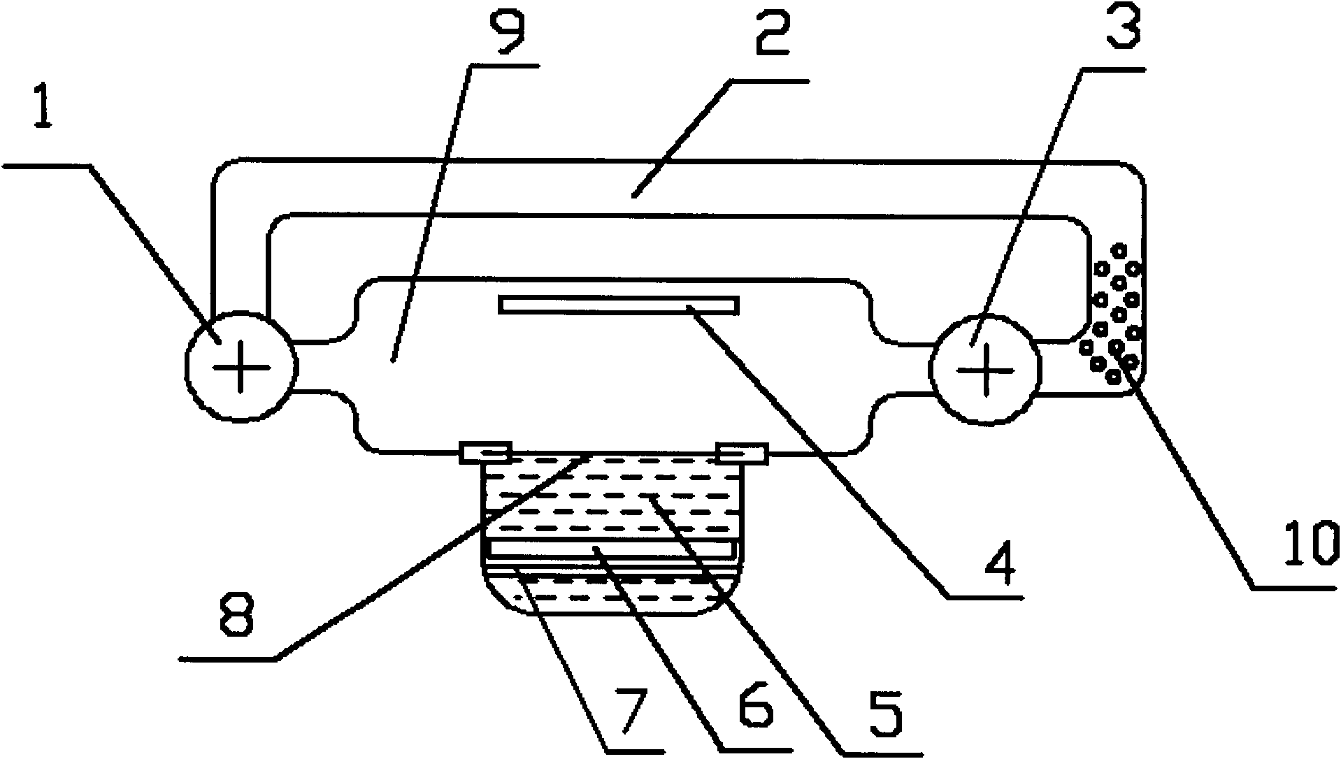
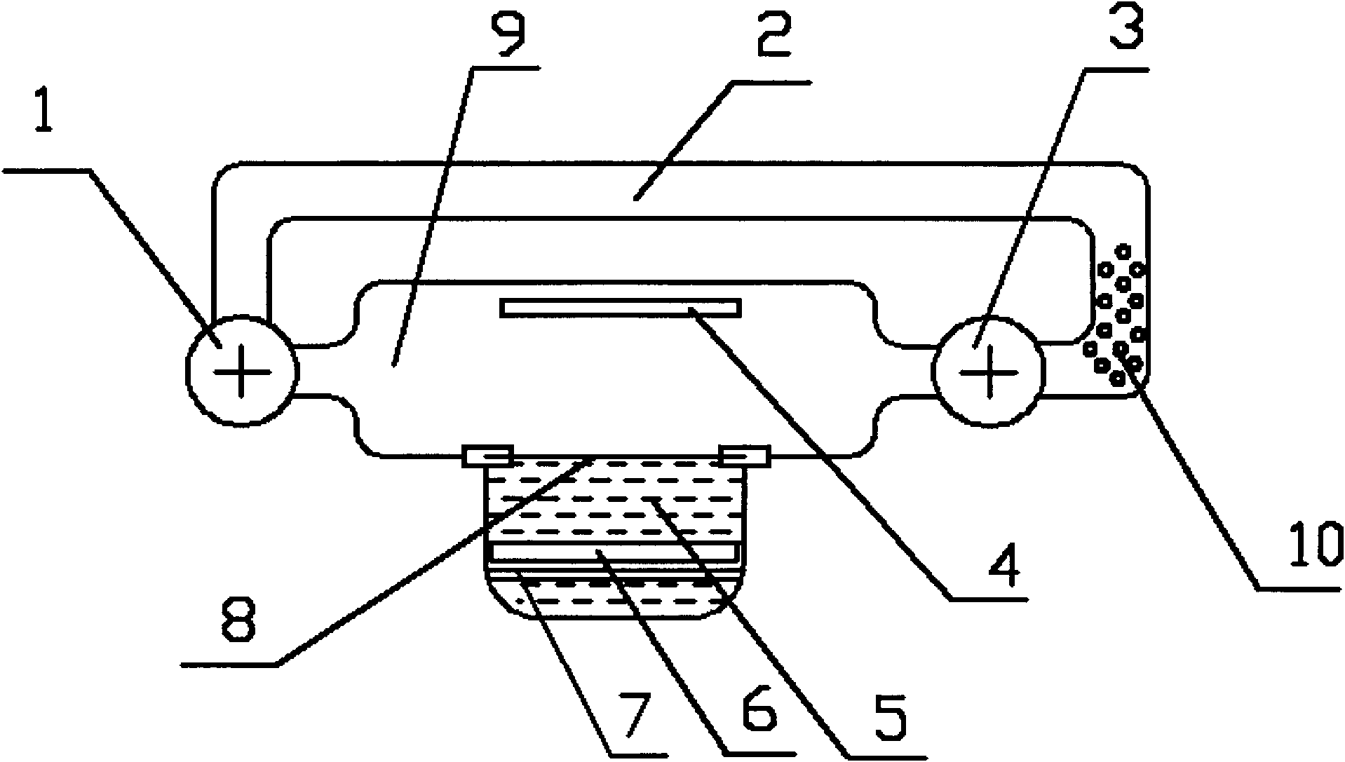
[0009] In the embodiment shown in the drawings, the membrane electrolysis tank includes a circulating booster pump 1, a circulating pipeline 2, a pressure reducing valve 3, a positive electrode 4, a hydrogen chamber 5, a negative electrode 7, a selective membrane 8, and a separation chamber 9, Said circulation booster pump 1 and pressure reducing valve 3 are arranged respectively at the inlet and outlet of said separation chamber 9, and said circulation booster pump 1 and pressure relief valve 3 are connected to said circulation pipeline 2 on the outside of separation chamber 9, so The side of the separation chamber 9 is provided with the hydrogen chamber 5, the hydrogen chamber 5 is separated from the separation chamber 9 by the selective membrane 8, the selective membrane 8 is a porous membrane, and its pore diameter is equivalent to that of hydrogen ions, only ...


PUM


Abstract

The invention provides a membrane-electrode electrolytic water tank which comprises a circulating booster pump, a circulating pipeline, a reducing valve, a positive electrode, a hydrogen chamber, a negative electrode, a selecting membrane and a separating chamber. The circulating booster pump and the reducing valve are respectively arranged at an inlet and an outlet of the separating chamber and connected with the circulating pipeline at the outer side of the separating chamber, the hydrogen chamber is arranged at one side of the separating chamber and separated from the separating chamber by the selecting membrane which only permits hydrogen ions to pass by, the hydrogen chamber is internally provided with the negative electrode and filled with uric acid, the positive electrode is arranged in a position corresponding to the negative electrode in the separating chamber, the hydrogen chamber is provided with a hydrogen outlet above the negative electrode, and the circulating pipeline is provided with an oxygen opening in a position close to the reducing valve. The membrane-electrode electrolytic water tank not only can effectively electrolyze water under a very low electrolytic voltage to prepare hydrogen and oxygen and has very high safety.

Description

Technical field [0001] The invention relates to the field of chemical industry, in particular to a membrane electrode water electrolysis tank for electrolyzing water. Background technique [0002] At present, in the field of chemical industry, in order to produce hydrogen and oxygen, electrolysis of water is often used. In this process, an electrolyzer is used. The working principle of an ordinary electrolyzer is as follows. Two opposite electrode plates are set in the water tank. , set a gas diaphragm between the plates, and then directly energize the water tank, so that the positively charged hydrogen ions move to the cathode plate, and the negatively charged hydroxide ions move to the anode plate, and oxidize at the cathode and anode plates respectively The reduction reaction produces hydrogen and oxygen, which are collected by its device. However, if the water used in this process is of high purity, the resistance of the water body is relatively high, and a large voltage...

Claims


Application Information

Patent Timeline
Patent Type & Authority Applications(China)
IPC IPC(8): C25B1/10C25B9/06C25B9/17
CPCY02E60/366Y02E60/36
Inventor 褚礼政
Owner 褚礼政
Learn More