Method for producing chemicals

Inactive Publication Date: 2009-10-08
FUJIFILM CORP
View PDF2 Cites 0 Cited by
  • Summary
  • Abstract
  • Description
  • Claims
  • Application Information

AI Technical Summary

Benefits of technology

[0009]The present invention has been made in the light of the circumstances. Accordingly, an object of the present invention is to provide a novel method for producing chemicals using a device which carries out reaction operations or unit operations for fluids flowing through a flow channel, in which the reaction operations or unit operations for object fluids can be controlled highly accurately and a functional fluid can be provided with various functions according to the type of reaction operations or unit operations for object fluids.
[0037]The present invention is applicable to the production of chemicals in general in which flow channels are utilized; however, it is particularly effective in the production of excellently monodisperse minute pigments.

Problems solved by technology

However, the technologies disclosed in Japanese Patent Application Laid-Open Nos. 2002-292274 and 2003-280126 are to provide fluids with functions (actions) of heat or vibration from outside of the flow channels, and they give rise to problems of having limitations in controlling reaction operations for the fluids flowing through the flow channels and in the types of functions they can provide the fluids.
These problems occur not only in devices which carry out reaction operations for fluids flowing through flow channels, but in devices which carry out unit operations (e.g. mixing, extraction, separation, heating, cooling, heat exchange, crystallization and absorption) to fluids flowing through flow channels.

Method used


Image

  • Method for producing chemicals
  • Method for producing chemicals
  • Method for producing chemicals

Examples


first embodiment

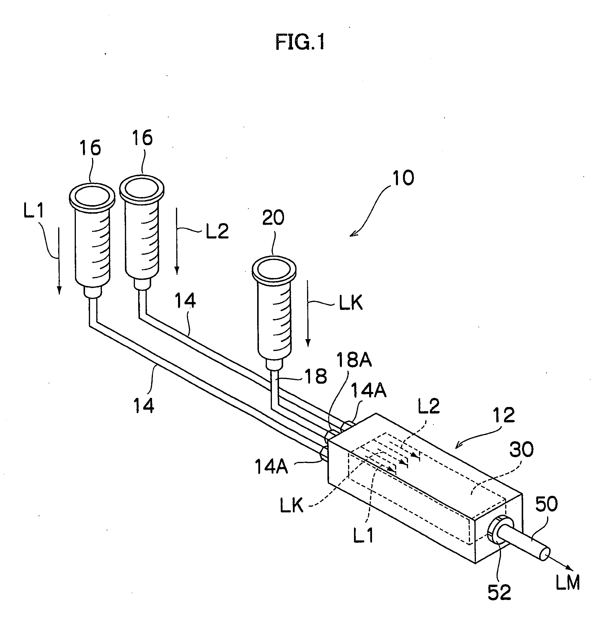
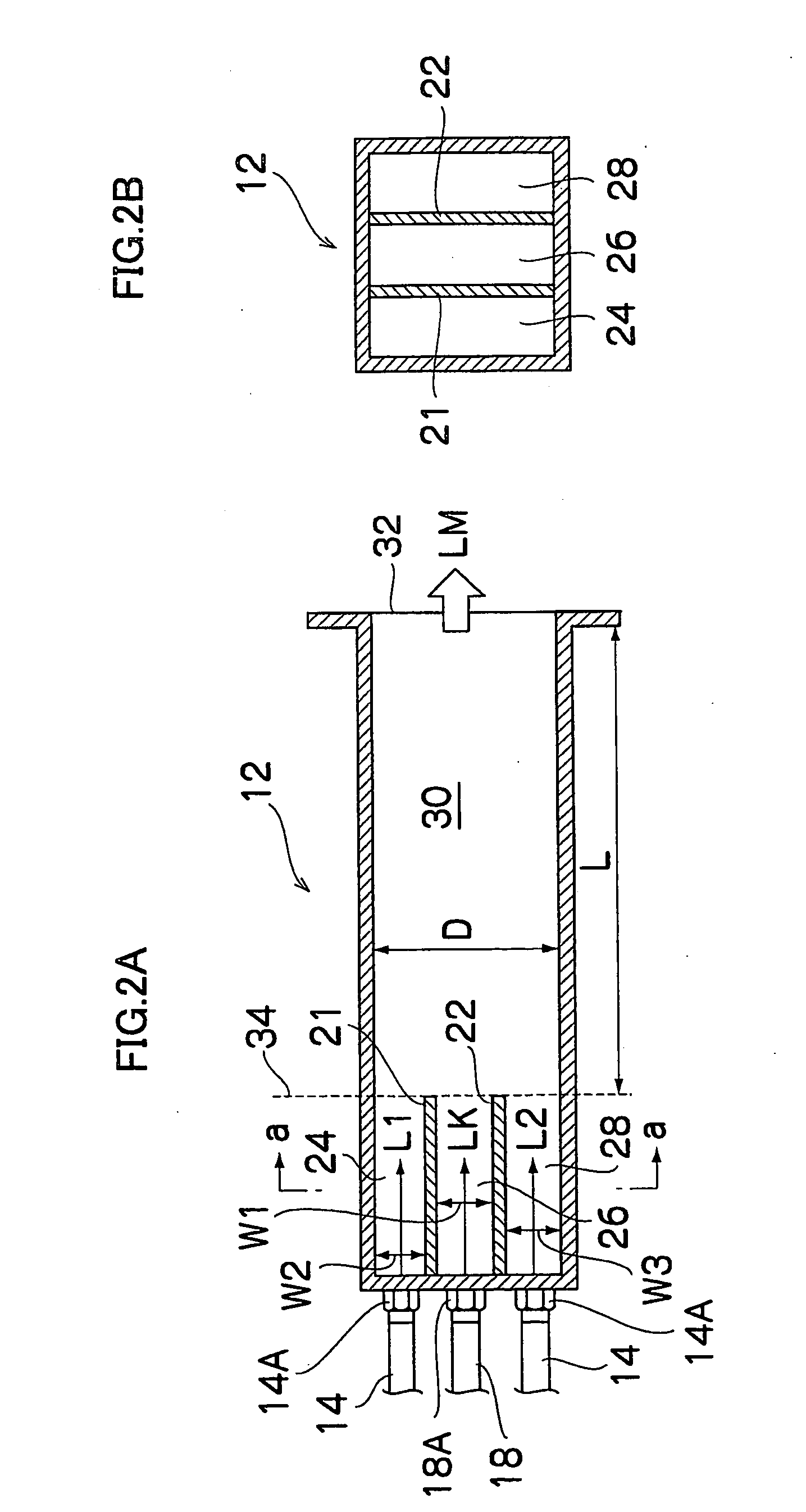
[0057]FIG. 1 is a conceptual diagram illustrating the entire structure of a production device 10 to which the method for producing chemicals in accordance with the present invention is applied. The device is so configured that three liquids L1, L2 and LK create laminar flows. FIG. 2A is a horizontal sectional view of the main body 12 of the device 10 and FIG. 2B a vertical sectional view of the main body 12 of FIG. 2A taken along the line a-a.

[0058]As shown in FIG. 1, the production device 10 with the laminar-flow configuration consists mainly of: the main body 12; liquid feeding device 16, 16 which feed the object liquids L1, L2 to the main body 12 through feeding pipes 14, 14; and functional-liquid feeding device 20 which feeds the functional liquid LK having a function of controlling the reaction operations or unit operations to the main body 12 through a feeding pipe 18. The feeding pipes 14, 18 are removably connected to the main body 12 via connectors 14A, 18A.

[0059]As shown i...

second embodiment

[0081]FIG. 4 is a conceptual diagram illustrating the entire structure of a production device 100 to which the method for producing chemicals in accordance with the present invention is applied. The device is so configured that three liquids (object liquids L1, L2 and a functional liquid LK) create flows annularly.

[0082]As shown in FIG. 4, the chemical production device 100 consists mainly of: a main body 111; liquid feeding device 16, 16 which feed the liquids L1, L2, as object liquid, to the main body 111 through feeding pipes 14, 14; and functional-liquid feeding device 20 which feeds the functional liquid LK having a function of controlling the reaction operations or unit operations to the main body 111 through a feeding pipe 18.

[0083]The main body 111 consists of: a plate 112, and a lid member 114 and a main body member 116 which are arranged in the upstream and in the downstream of the plate 112, respectively, so as to hold the plate 112 between them, as shown in FIGS. 5 and 6...

example

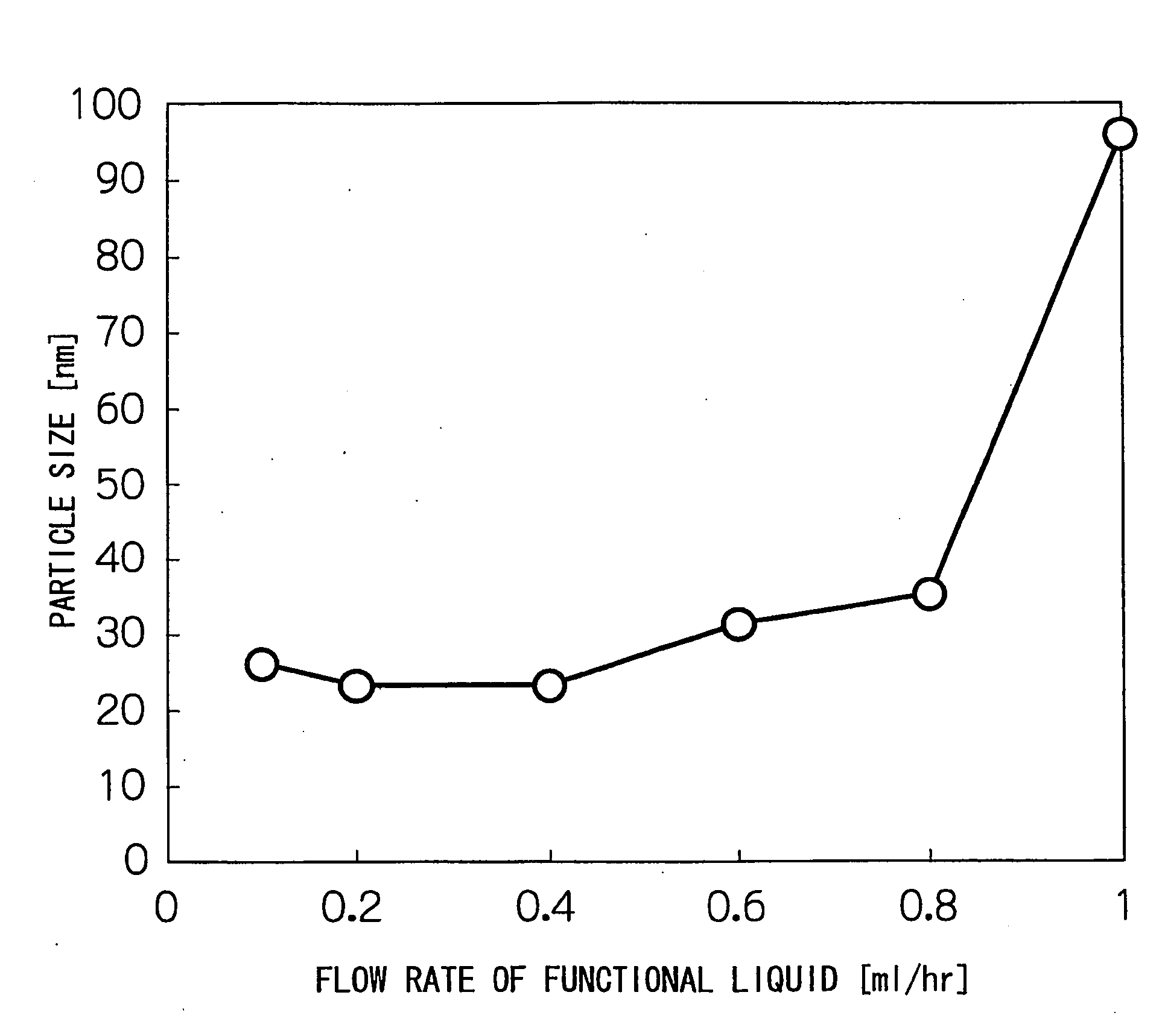
[0101]Pigment particles were produced using a production device 100 forming an annular flow as described in FIGS. 4 to 10. As a flow channel 128, a flow channel having an equivalent diameter of 1 mm or less was selected so that object liquids L1, L2 and a functional liquid LK flow laminarly through the flow channel 128.

[0102]The object liquid L1 was a solution of dimethyl sulfoxide (DMSO), PVP as a polymer, 0.8 mole of KOH as an alkaline agent, and Pigment Red as a pigment. The pigment concentration was 1.0% by weight.

[0103]The object liquid L2 was a solution of N-oleyl-N-methyltaurine sodium salt (manufacturer: Sankyo Chemical Co., Ltd.) as a surfactant and water. The surfactant concentration was 0.84% by weight.

[0104]The functional liquid LK was a solution of 0.8 mole of KOH as an alkaline agent and PVP as a polymer in dimethyl sulfoxide (DMSO).

[0105]These liquids L1, L2 and LK were fed to the production device 100, and a concentric 3-layer flow structure having a functional layer...


PUM

PropertyMeasurementUnit
Thicknessaaaaaaaaaa
Thicknessaaaaaaaaaa
Diameteraaaaaaaaaa

Abstract

There is provided a method for producing chemicals using a device which carries out reaction operations or unit operations for fluids flowing through a flow channel, in which the reaction operations or unit operations for the object fluids can be controlled highly accurately, and besides, a functional fluid can be provided with various functions according to the type of the reaction operations or unit operations. The method produces chemicals using a device 10 in which a plurality of object liquids L1, L2 are fed through respective fluid-feeding channels 24, 28 therefor and joined together in a single flow channel 30 to carry out reaction operations or unit operations, the method including forming a functional layer between the object fluids by allowing a functional fluid having a function of controlling the reaction operations or unit operations to flow through the flow channel.

Description

TECHNICAL FIELD[0001]The present invention relates to a method for producing chemicals, in particular, to a technology for producing chemicals using a device that allows a plurality of fluids to flow through a single flow channel to carry out reaction operations or unit operations.BACKGROUND ART[0002]In recent years, technologies for producing chemicals by reacting a plurality of fluid with each other while allowing the fluids to flow through a single flow channel have been in the limelight in areas such as, for example, the chemical industry or the pharmaceutical industry, where pharmaceuticals, reagents and the like are produced. One typical example of such technologies is microchemical devices such as microreactors. Microreactors are devices embodying a technology for continuously producing chemicals as reaction products by reacting a plurality of fluid with each other while allowing the fluids to flow laminarly through a flow channel whose cross-section is very small. Unlike bat...

Claims


Application Information

Patent Timeline
IPC IPC(8): C08K5/23
CPCB01F13/0067B01J19/0093B01J2219/00788B01J2219/00822B01J2219/00824B01J2219/00828B01J2219/00984B01J2219/00833B01J2219/0086B01J2219/00873B01J2219/00891B01J2219/00907B01J2219/00952B01J2219/00831B01F33/30121B01J19/00B81B1/00
Inventor UEYAMA, TOMOHIDENAGASAWA, HIDEHARUICHIKAWA, YASUNORI
Owner FUJIFILM CORP
Why Eureka
Try Eureka