
All-fiber current transducer

A current transformer and all-optical fiber technology, applied in the direction of voltage/current isolation, etc., can solve the problems of high processing precision of the sensor head, difficulty in meeting the actual requirements of measurement accuracy reliability, low sensitivity, etc. The influence of stable factors, the realization of spectrum shift, and the effect of improving detection accuracy

Inactive Publication Date: 2011-01-26
淄博思科电子技术开发有限公司
View PDF6 Cites 11 Cited by
  • Summary
  • Abstract
  • Description
  • Claims
  • Application Information

AI Technical Summary

Problems solved by technology

The bulk glass-type OCT was developed to overcome the low sensitivity and linear birefringence problems of fiber-optic OCT. The main disadvantages are that the processing accuracy of the sensor head is high, it is easy to break during processing, and the optical path coupling is difficult, so the cost is relatively high. High, not easy to industrialize
The hybrid current transformer uses the traditional electromagnetic transformer as the sensing head, and the optical fiber is only used for signal transmission. The problem is that the sensing head part involves the active circuit, and the power supply is quite difficult. Essentially solve the problem of electromagnetic interference
[0005] The all-fiber current transformer in the prior art generally achieves the purpose of measuring current by changing the polarization state of linearly polarized light through polarization measurement technology. In this measurement method, due to the non-reciprocity of the optical transmission path, the system is vulnerable to Effects of fiber birefringence, ambient temperature, vibration and other factors
It has been difficult for OCT with this structure to meet the actual requirements in terms of measurement accuracy and long-term operation reliability for a long time.

Method used


Image

  • All-fiber current transducer
  • All-fiber current transducer

Examples


Embodiment Construction

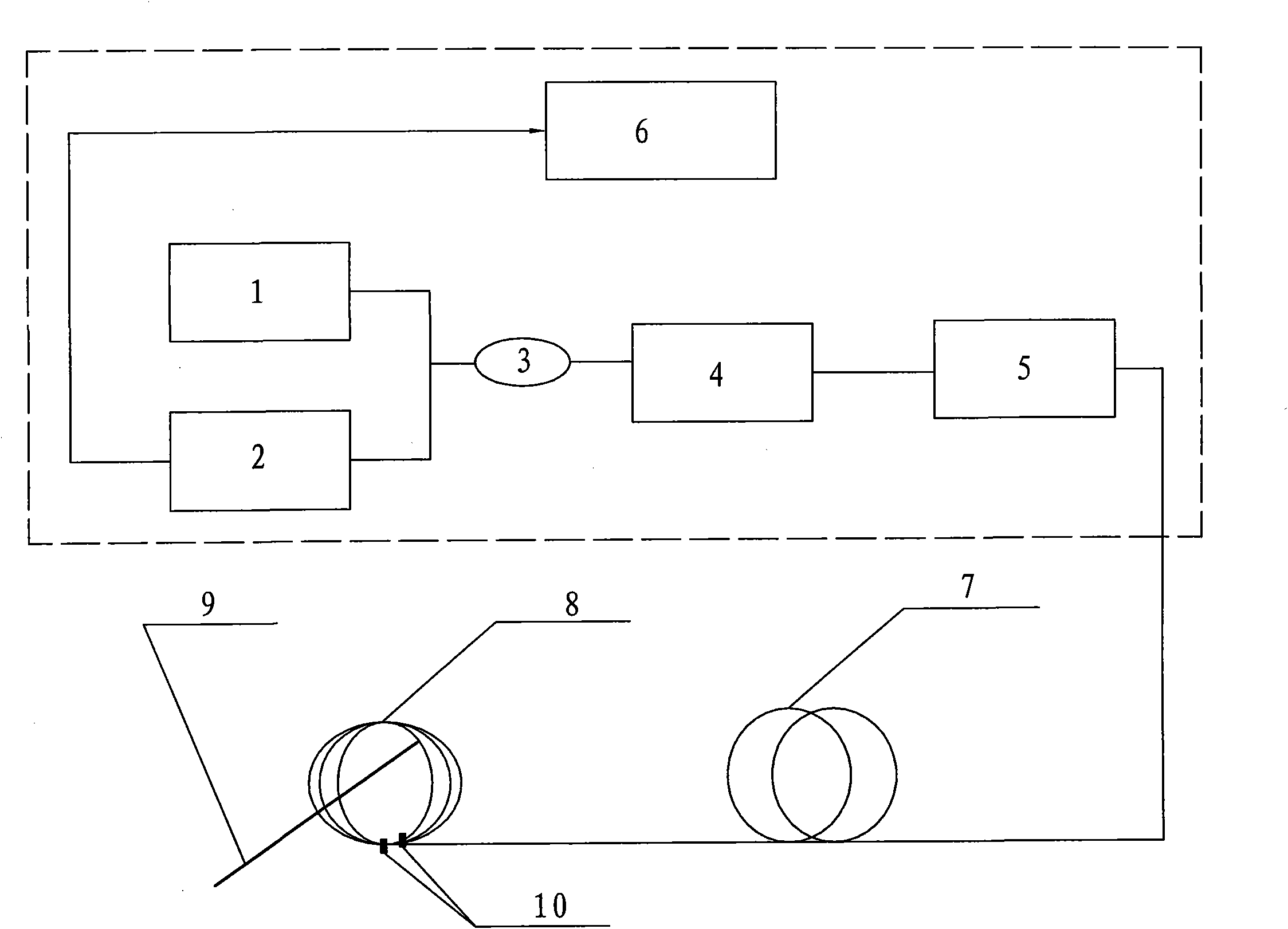
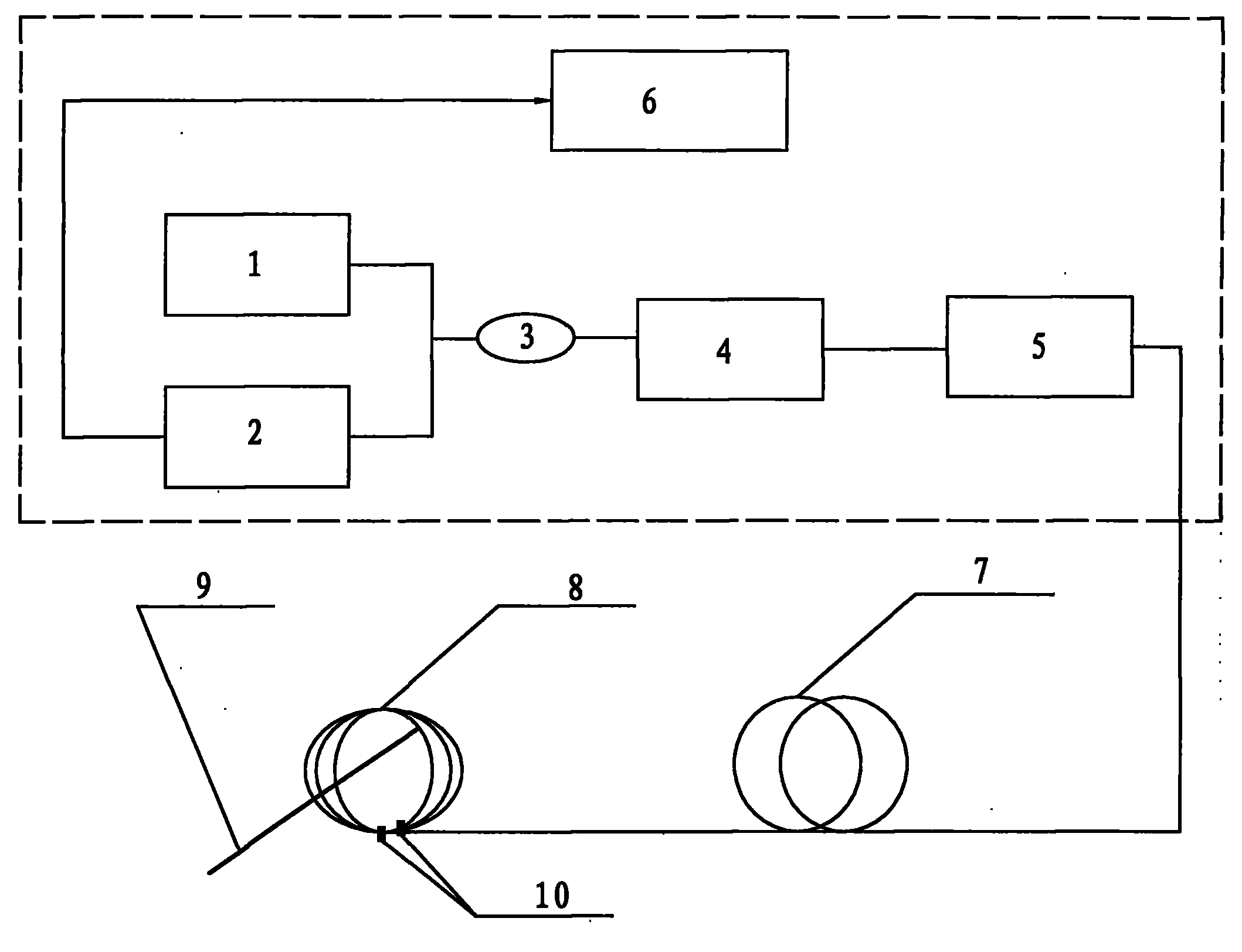
[0018] Such as figure 1 As shown, the light emitted by the light source 1 is sent into the optical fiber, and the optical signal is divided into two optical signals by the optical coupler 3 , and then divided into two linearly polarized lights whose polarization states are perpendicular to each other in the polarizer 4 . The two linearly polarized lights are modulated by the polarized light modulator 5 to eliminate the influence of power, and then sent to the Faraday reflector 10 through the polarization-maintaining fiber 7, and the two mutually perpendicular linearly polarized lights are respectively converted into right-handed and left-handed circularly polarized light, and sent into the sensing fiber 8 surrounding the current wire 9, according to the Faraday effect, the induced magnetic field around the current wire 9 will cause the right-handed and left-handed circularly polarized light passing through the magnetic field to have different transmission speeds. The magnitude...


PUM


Abstract

The invention discloses an all-fiber current transducer, belonging to the field of electric power measurement and comprising a sensing optical fiber and an electronic sensor which are connected by an optical cable. The all-fiber current transducer is characterized in that the electronic sensor comprises a light source, an optical coupler, a polarizer and a polarized light modulator which are sequentially connected by a cable. The electronic sensor further comprises a differential light receiving device connected with the optical coupler by the cable; the differential light receiving device is also electrically connected with a signal processor; and two Faraday reflecting mirrors are arranged on the sensing optical fibers. The invention can effectively inhibit the influences from double refraction of the optical fiber, the temperature, the vibration and the like and has the potential for realizing high precision and highly reliable measurement.

Description

technical field [0001] The invention belongs to the field of electric power measurement, in particular to an all-fiber current transformer. Background technique [0002] In power systems, the need for metering and protection makes real-time measurement of the current in high-voltage transmission lines a must. The traditional high-voltage current measurement system is an oil-filled current transformer (CT for short). Its sensing probe uses the principle of electromagnetic induction, and the signal is transmitted through wires. The main disadvantages are that it is susceptible to electromagnetic interference and difficult to insulate. In order to solve the problems of high-voltage isolation and electromagnetic interference, the transmission line is very heavy, and the entire system is bulky and expensive. In contrast, optical current transformers (Optical Cutrent Transducers, referred to as OCT), which have received wide attention in recent years, are considered to be the pre...

Claims


Application Information

Patent Timeline
IPC IPC(8): G01R15/24
Inventor 耿玉桐王波
Owner 淄博思科电子技术开发有限公司
Learn More