Microwave antenna and outer cover thereof

A microwave antenna and cover technology, which is applied to antennas, radiating unit covers, electrical components, etc., can solve the problems of limited frequency bandwidth, disturbing the distribution of diffraction fields, and increasing the overall size of the antenna, so as to achieve low packaging and transportation costs and improve Side lobe level and low processing cost

Active Publication Date: 2011-01-26
COMBA TELECOM SYST (GUANGZHOU) LTD
View PDF3 Cites 162 Cited by
  • Summary
  • Abstract
  • Description
  • Claims
  • Application Information

AI Technical Summary

Problems solved by technology

[0008] 1) The loss of antenna gain is mainly caused by the insertion loss introduced by the radome. Therefore, it is required not only to choose a low-loss dielectric material but also to design its thickness reasonably to achieve the best wave transmission performance when designing the radome;
[0009] 2) Increase the return loss of the antenna, that is, deteriorate the input voltage standing wave ratio (VSWR) of the antenna, which is mainly caused by the reflected electromagnetic wave caused by the radome returning to the feed source;
[0011] 4) Deteriorating the F/B performance of the antenna, which is mainly due to the fact that the radome disturbs the diffraction field distribution at the edge of the antenna mouth, and even the radome plays a role of "guiding" the diffraction field backwards, thereby improving the antenna's back radiation
[0013] 1) The frequency bandwidth is limited, so it is not suitable for broadband antenna syst

Method used


Image

  • Microwave antenna and outer cover thereof
  • Microwave antenna and outer cover thereof
  • Microwave antenna and outer cover thereof

Examples


Embodiment Construction

[0048] Below in conjunction with accompanying drawing and embodiment the present invention will be further described:

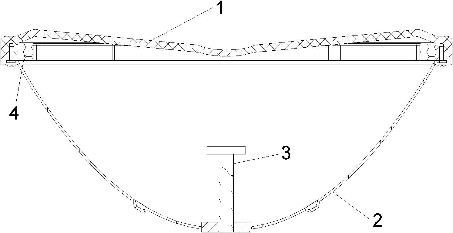
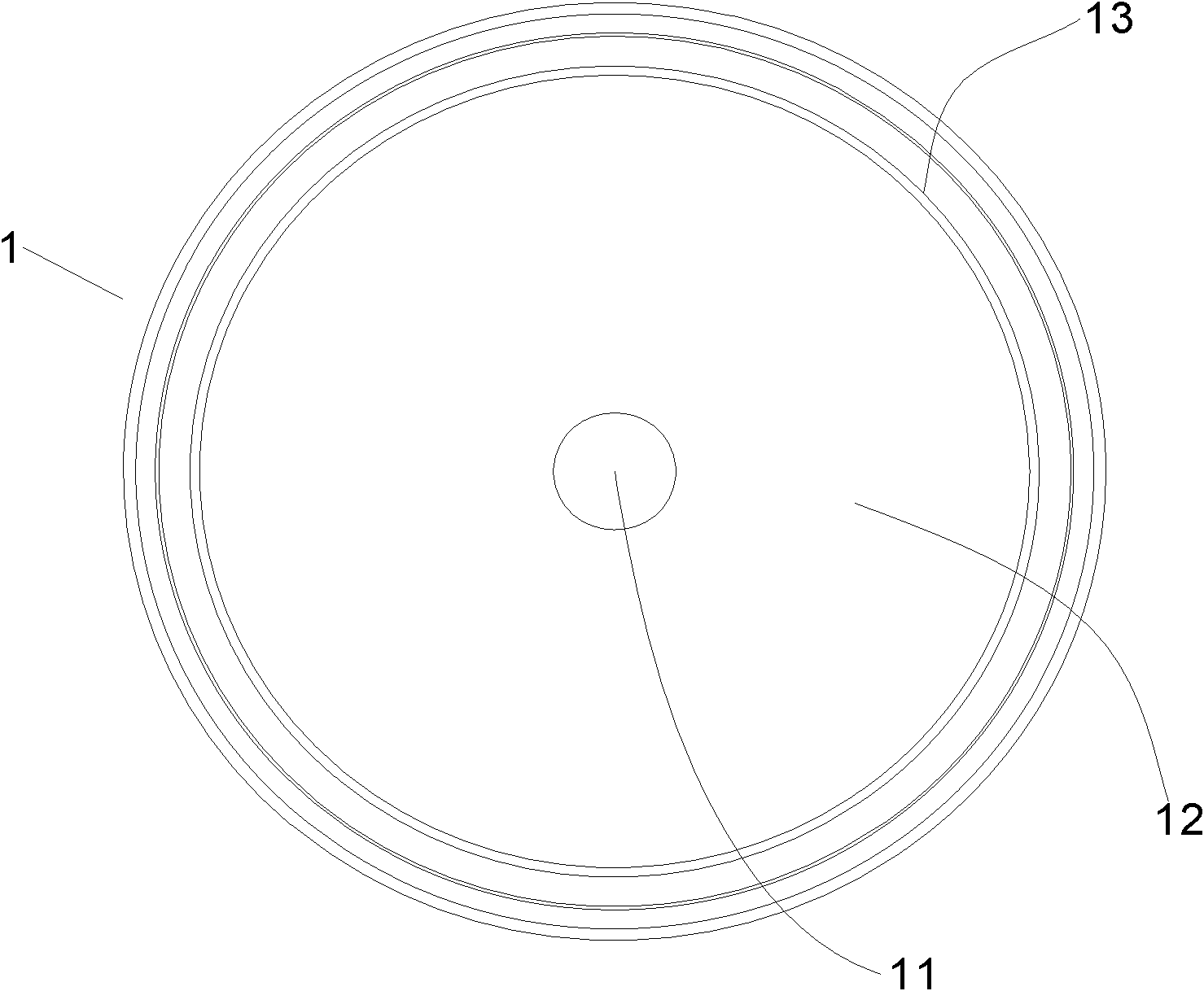
[0049] see figure 2 , image 3 and Figure 4 A microwave antenna to which the microwave antenna cover of the present invention is applied includes: a shape-dielectric antenna cover 1 with a rotationally symmetrical structure, several mounting studs 14 and several limiting clips 15 , and a wave-absorbing material 4 . The housing 1 is secured by additional screws 5 (see Figure 11 ) is connected to the flange of the microwave antenna reflection surface 2, and is positioned by the limiting clip 15. The housing 1 has several concentric components distributed sequentially outward from its axis of rotational symmetry: a compensating part 11 located in the central area, a main reflective part 12 continuing from the compensating part to form the periphery of the compensating part, and a continuation from the main reflecting part Each of the secondary reflective ...


PUM


Abstract

The invention discloses a microwave antenna and an outer cover thereof. The outer cover is a rotational symmetric element which comprises a plurality of homocentrically arranged parts as below: a compensation part arranged at the middle of the outer cover and used for compensating the phase delay of the electric field distribution at the middle of an antenna aperture surface caused by the shielding of a feed source, a main reflection part arranged at the periphery of the compensation part and used for reflecting the electromagnetic wave emitted from the microwave antenna feed source to a specific direction deviating from the feed source, and an assistant reflection part arranged at the periphery of the main reflection part and used for carrying out reflex bunching on the edge diffraction electromagnetic wave of the microwave antenna. All the parts of the outer cover are especially designed and shaped, therefore the microwave antenna has the characteristics of excellent electrical properties, stable structure, low cost and the like.

Description

【Technical field】 [0001] The invention relates to the field of communication antennas, in particular to a microwave antenna and its outer cover. 【Background technique】 [0002] With the increasing demand for microwave communication, the point-to-point or point-to-multipoint communication network composed of microwave antennas is becoming more and more dense, and the potential risk of mutual interference between microwave systems is increasing. To this end, various administrative authorities and network operators have formulated strict standards to limit the radiation pattern envelope (Radiation Patterns Envelope, RPE) of microwave antennas, and then select antennas that meet different standard levels according to different network requirements. Among the electrical performance indicators of the antenna, the Front-to-Back Ratio (F / B) is particularly important and must be considered in the design of the antenna. [0003] The radome is an important component of the microwave a...

Claims


Application Information

Patent Timeline
IPC IPC(8): H01Q1/42H01Q19/18H01Q19/19
CPCH01Q19/19H01Q19/134H01Q19/18H01Q1/42
Inventor 吴知航姜汝丹刘素芹唐荣谢庆南王勇潘军王岩符道临
Owner COMBA TELECOM SYST (GUANGZHOU) LTD
Why Eureka
Try Eureka