Surface treatment apparatus

A technology of surface treatment device and supply device, applied in feeding device, chemical/physical process, chemical/physical/physical-chemical process, etc., can solve the problems of increased calorific value, corrosion, pump damage, etc. The effect of suppressing uneven treatment

Inactive Publication Date: 2014-11-05
TOYO TANSO KK
View PDF3 Cites 0 Cited by
  • Summary
  • Abstract
  • Description
  • Claims
  • Application Information

AI Technical Summary

Problems solved by technology

As we all know, the fluorine gas is a highly reactive, toxic and corrosive gas. When the gas containing a large amount of fluorine gas is discharged from the treatment tank for a while, it may be caused by the increase in the calorific value of the pesticide used to treat the fluorine gas. Large, etc., the load is applied to the piping, components, equipment, pesticides, etc. installed downstream of the treatment tank, and local heat is generated, or the piping, etc. are corroded as a result.
In particular, there is also an exhaust device for exhausting gas from the reactor on the downstream side of the reactor, and the pump installed on the exhaust device may be damaged.

Method used


Image

  • Surface treatment apparatus
  • Surface treatment apparatus
  • Surface treatment apparatus

Examples


no. 1 Embodiment approach

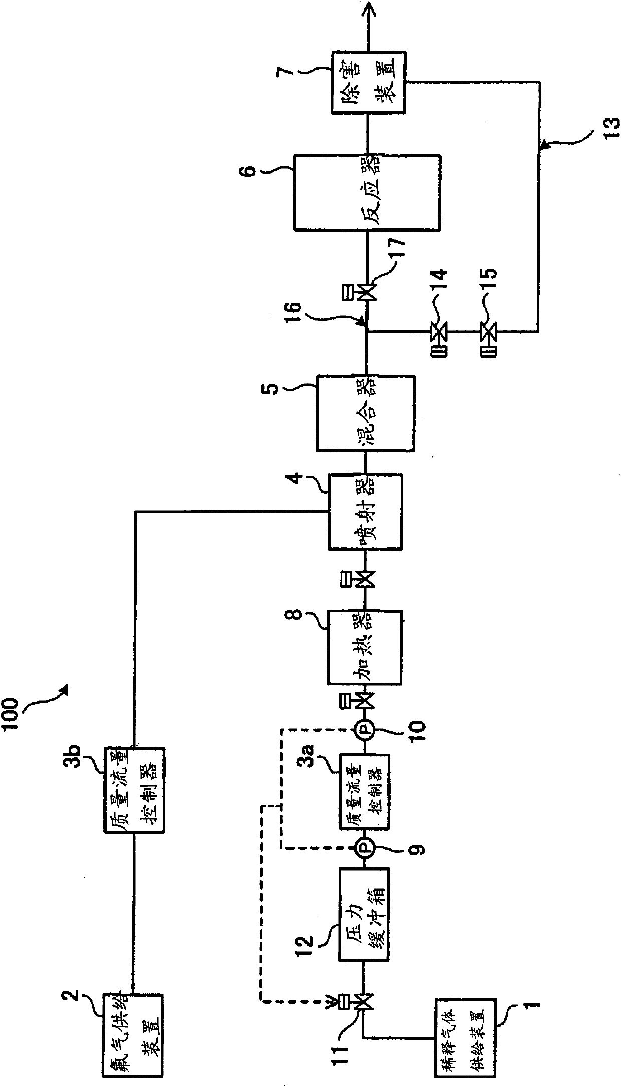
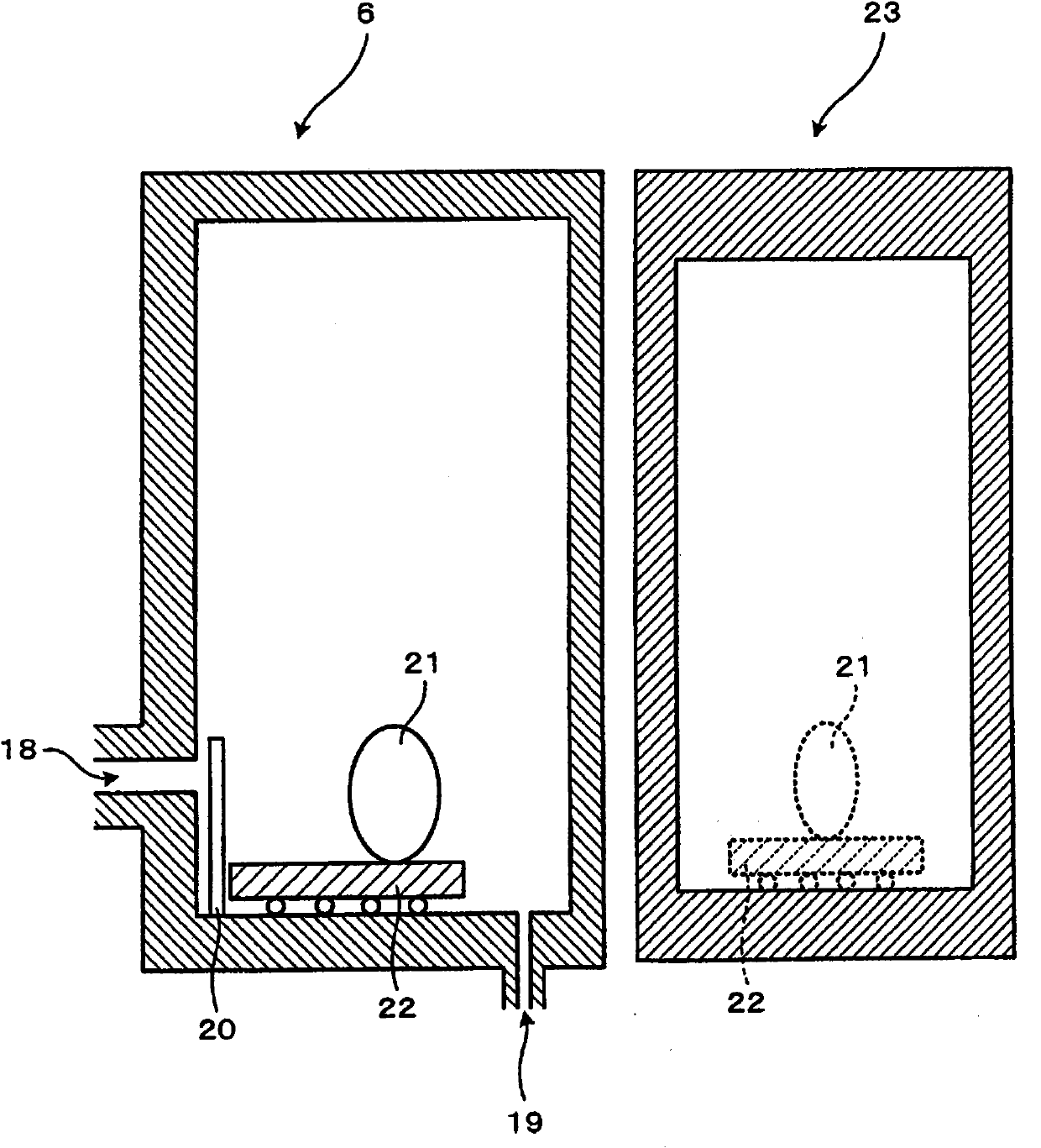
[0068] Here, a first embodiment of the surface treatment device of the present invention will be described. figure 1 It is a schematic configuration diagram of main parts of a surface treatment device according to an embodiment of the present invention, figure 2 yes figure 1 A schematic cross-sectional view of the reactor.

[0069] figure 1 Among them, the surface treatment device 100 includes: a dilution gas supply device 1, a fluorine gas supply device 2, a mass flow controller (first flow rate adjustment mechanism) 3a connected to the dilution gas supply device 1 via piping, and a fluorine gas supply device via piping. Two mass flow controllers (second flow adjustment mechanism) 3b connected to each other are connected to the injector 4 connected to the mass flow controllers 3a and 3b through pipes, respectively, and the injector 4 is connected to the injector 4 through pipes and installed on the downstream side of the injector 4 The mixer 5, the reactor 6 for treating ...

no. 2 Embodiment approach

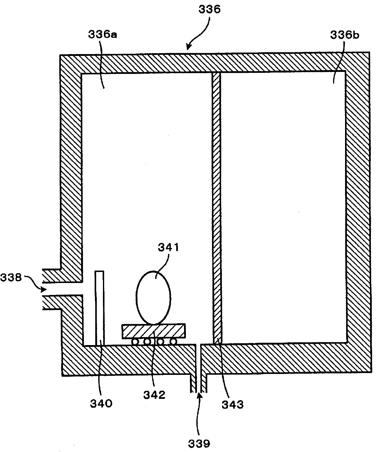
[0107] Here, a second embodiment of the surface treatment device of the present invention will be described. image 3 It is a schematic structural view of the main part of the surface treatment apparatus of 2nd Embodiment. In addition, since the same reference numerals as in the first embodiment are basically the same components as in the first embodiment, description thereof will be omitted.

[0108] image 3 Among them, the surface treatment device 200 includes: a dilution gas supply device 1, a fluorine gas supply device 2, a mass flow controller (first flow adjustment mechanism) 3a connected to the dilution gas supply device 1 via piping, and a fluorine gas supply device via piping. Two mass flow controllers (second flow adjustment mechanism) 3b connected to each other are connected to the injector 4 connected to the mass flow controllers 3a and 3b through pipes, respectively, and the injector 4 is connected to the injector 4 through pipes and installed on the downstream ...


PUM


Abstract

A surface treatment apparatus 100 includes a diluent gas supplier 1, a fluorine gas supplier 2, a mixer 5 which mixes a diluent gas with a fluorine gas, and a reactor 6 which treats a treatment target by using a mixed gas generated by the mixer 5. A diluent gas supplied from a diluent gas supplier is heated by a heater 8, and the heated diluent gas is mixed with a fluorine gas supplied from a fluorine gas supplier, in the mixer 5. The mixed gas is supplied to the reactor 6. The gas in the reactor 6 is supplied from the reactor 6 to flow paths 219, 220, 221, and 222 by an exhauster 207. The valves 223, 224, 225, and 226 are serially opened, so that the gas in the reactor 6 is supplied to a harm removal apparatus 208 while the gas flow rate is being adjusted by the flow paths 219, 220, 221, and 222.

Description

technical field [0001] The invention relates to a surface treatment device for surface treatment, surface modification and the like of a sample by using fluorine gas. Background technique [0002] Conventionally, surface modification or surface treatment for treating organic substances etc. with fluorine gas has been performed. For example, surface treatment apparatuses shown in the following patent documents are known. The surface treatment device disclosed in Patent Document 1 includes a gas adjustment tank with supply pipes respectively connected with a fluorine gas source and an inert gas source, a treatment tank connected with the above-mentioned gas adjustment tank through a gas conduit, and a waste gas treatment device, which is suitable for Small-scale surface treatment or surface treatment with dilute fluorine gas. [0003] Patent Document 1: JP-A-2000-319433 [0004] In the case of using a large-capacity treatment tank for surface treatment, treatment unevenness ...

Claims


Application Information

Patent Timeline
Patent Type & Authority Patents(China)
IPC IPC(8): B01J19/00B01D53/68C08J7/12C23C8/08H01L21/3065
CPCH01L21/3065H01L21/67017H01L21/67109H01L21/6719B01J4/008
Inventor 平岩次郎竹林仁吉本修田中则之藤田一郎佐佐木启能森一高
Owner TOYO TANSO KK
Why Eureka
Try Eureka