Anti-glare film, anti-glare polarizing plate and image display device

An anti-glare film and anti-glare technology, used in polarizing elements, nonlinear optics, optics, etc., can solve problems such as difficulty in achieving high contrast, and achieve the goal of preventing the reduction of visibility, excellent anti-glare performance, and high contrast. Effect

Inactive Publication Date: 2011-01-26
SUMITOMO CHEM CO LTD
View PDF7 Cites 26 Cited by
  • Summary
  • Abstract
  • Description
  • Claims
  • Application Information

AI Technical Summary

Problems solved by technology

[0012] However, with any of the antiglare films described in Patent Documents 5 to 7, it is difficult to achieve high contrast when used in a high-definition image display device.

Method used


Image

  • Anti-glare film, anti-glare polarizing plate and image display device
  • Anti-glare film, anti-glare polarizing plate and image display device
  • Anti-glare film, anti-glare polarizing plate and image display device

Examples


Embodiment 1

[0158] (A) Preparation of the mold for the first resin layer

[0159] A product in which copper ballard plating (copper ballard plating) was performed on the surface of an iron roll (JIS STKM13A adopted) with a diameter of 200 mm was prepared. Copper Ballard coating consists of copper coating / thin silver coating / surface copper coating, and the overall thickness of the coating is about 200μm. The surface of its surface copper plating layer is mirror-polished, and then this grinding surface, use sand blasting device (manufactured by Fuji Manufacturing Co., Ltd.), with the amount of beads 8g / cm 2 (every 1cm 2 The usage amount of the surface area of ​​the roller, hereinafter referred to as "blasting amount"), blasting pressure 0.2MPa (gauge pressure, the same below), the distance from the nozzle for spraying beads to the metal surface 300mm (hereinafter referred to as "blasting distance") ") Zirconia beads "TZ-SX-17" (trade name, average particle diameter: 17 μm) manufactured by...

Embodiment 2

[0170] Using the above-mentioned resin composition (b) in the first resin layer, and using the above-mentioned resin composition (a) in the second resin layer, in the same manner as in Example 1, a combination of the first and second resin layers and the TAC film was produced. Anti-glare film composed of a laminate. The die (A) was used to form the uneven surface of the first resin layer, and the die (B) was used to form the uneven surface of the second resin layer, which was the same as in Example 1.

Embodiment 3

[0193] Except having formed the 2nd resin layer using the mold (E), it carried out similarly to Example 1, and produced the antiglare film which consists of the laminated body of the 1st and 2nd resin layer, and a TAC film. The resin composition (a) is used for the first resin layer, and the resin composition (b) is used for the second resin layer. The mold (E) was produced in the same manner as the mold (A) except that the blasting pressure and the amount of etching were the values ​​shown in Table 2.


PUM

PropertyMeasurementUnit
Thicknessaaaaaaaaaa

Abstract

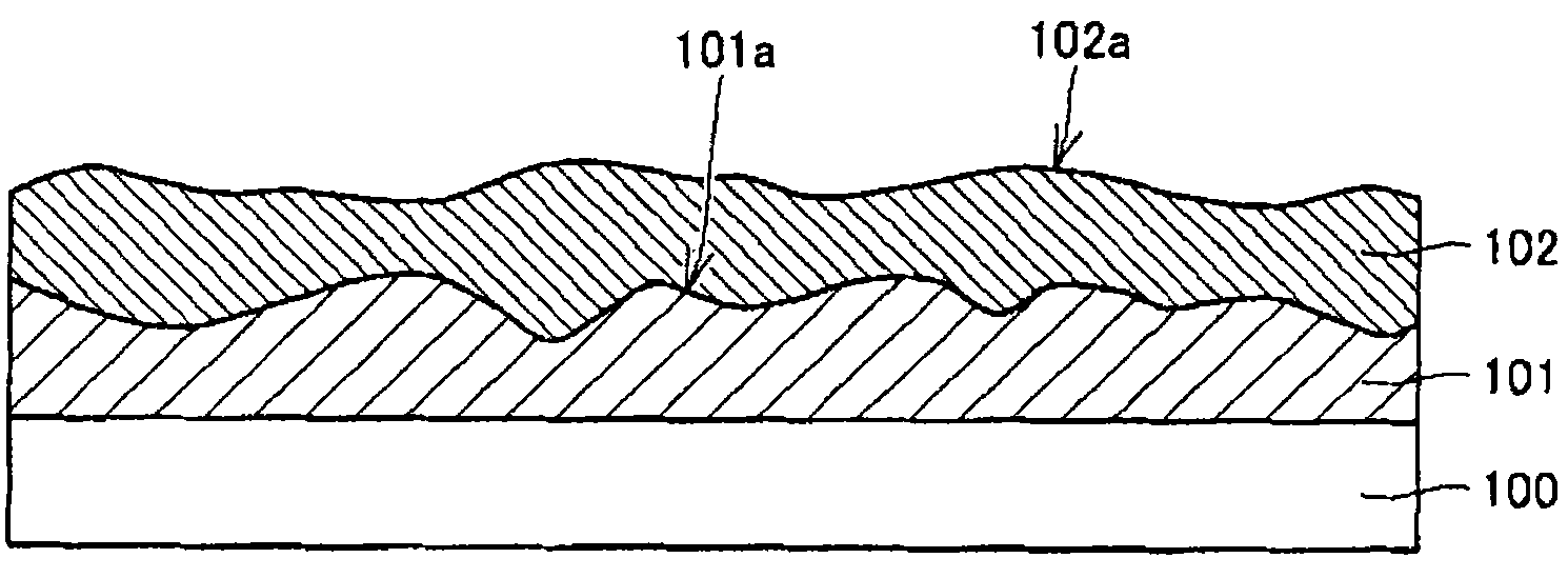
Provided are an anti-glare film provided with a transparent support (100), a first resin layer (101) stacked on the transparent support (100), and a second resin layer (102) stacked on the first resin layer (101), wherein the first resin layer (101) and the second resin layer (102) have refractive indexes different from each other, the first resin layer (101) is formed of an ionizing radiation-cured resin provided with fine depressions and projections on the surface thereof on the side opposite to the transparent support (100) side, the second resin layer (102) is formed of the ionizing radiation-cured resin provided with fine depressions and projections on the surface thereof on the side opposite to the transparent support (100) side, and the internal haze is 5% or more and 30% or less, an anti-glare polarizing plate using the same, and an image display device.

Description

technical field [0001] The present invention relates to an antiglare film that exhibits excellent antiglare performance, is free from whitening, does not cause glare when applied to an image display device, exhibits high contrast, and imparts good visibility, and an antiglare film using the antiglare film Antiglare polarizing plate and image display device. Background technique [0002] For image display devices such as liquid crystal displays, plasma display panels, Braun tube (cathode ray tube: CRT) displays, and organic electroluminescent (EL) displays, when external light shines on the display surface, visibility is significantly impaired. Conventionally, in order to prevent the reflection of such external light, in TVs and personal computers that value image quality, video cameras and digital cameras used outdoors where external light is strong, and mobile phones that use reflected light to display, image display The surface of the device is provided with a film layer ...

Claims


Application Information

Patent Timeline
IPC IPC(8): G02B5/02G02B5/30G02F1/1335
CPCG02B1/111G02F1/133502G02B5/305
Inventor 古谷勉丰岛麻利
Owner SUMITOMO CHEM CO LTD
Why Eureka
Try Eureka