PECVD system with internal heater

An internal heater and heating tube technology, applied in the field of PECVD system, can solve the problems of hidden safety hazards and inconvenient operation of workers, and achieve the effects of simple and compact structure, temperature maintenance, and easy production.

Inactive Publication Date: 2011-02-02
SHENZHEN GLOBAL SOLAR ENERGY TECH
View PDF0 Cites 20 Cited by
  • Summary
  • Abstract
  • Description
  • Claims
  • Application Information

AI Technical Summary

Problems solved by technology

The movable plasma box is mainly made of stainless steel. The weight of such a portable plasma box can reach more than 500Kg. Due to its own weight, it must be operated manually for non-automatic continuous production, which makes the portable plasma box move in. , It is inconvenient for workers to operate when moving out, and there are potential safety hazards

Method used


Image

  • PECVD system with internal heater
  • PECVD system with internal heater
  • PECVD system with internal heater

Examples


Embodiment 1

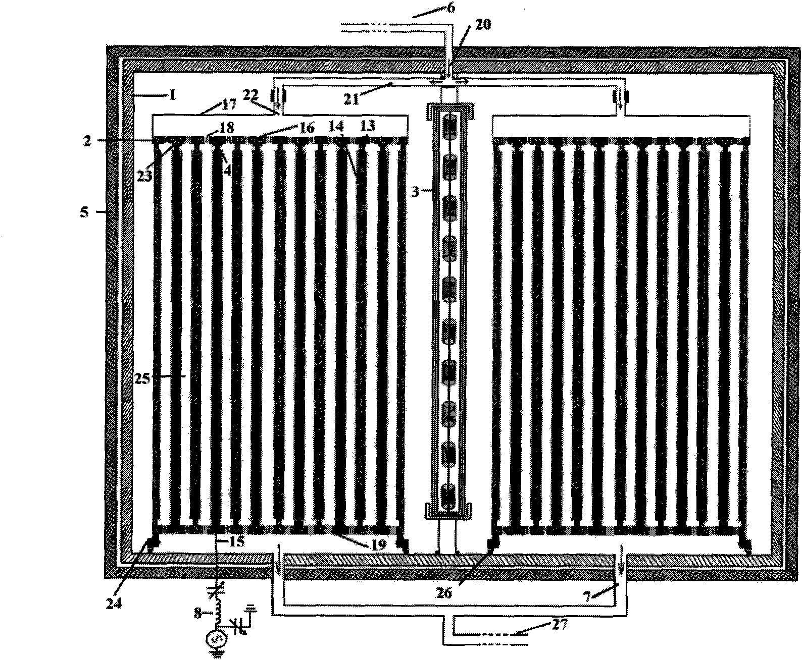
[0036] PECVD system of the present invention adopts computer control, as Figure 3a As shown, the PECVD system adopts a single vacuum chamber, and the vacuum chamber 1 is a rectangular stainless steel outer shell, and its upper end is provided with an air inlet 20, and its lower end is provided with an air outlet 7, and a heating plate 5 is attached on the outer four walls of the vacuum chamber. It is better to adopt an electric heating plate known in the prior art, and the heating plate 5 is in close contact with the outer four walls of the vacuum chamber through a mechanical fastening mechanism (such as rivets or screws), so as to obtain effective heat transfer to the wall surface of the vacuum chamber, and then The movable plasma box 2 in the vacuum chamber is evenly heated. The gas inlet 20 is used to communicate with the gas inlet system 6 so as to input the working gas into the plasma box, and the gas outlet 7 is used to communicate with the pumping system 27 so as to su...

Embodiment 2

[0047] The structure and operation process of the PECVD system described in this example are basically the same as embodiment 1, only difference is:

[0048] Such as Figure 3b As shown, the PECVD system described in this example uses a single vacuum chamber. Two movable plasma boxes are placed in parallel in the vacuum chamber. Each movable plasma box has 8 excitation electrodes and can carry 32 substrates. The whole system can Install 64 substrates, the substrate area is 381×1270mm, there is an internal heater in the middle of the two movable plasma boxes, the size of the heating device is 1500×760×20mm, and the heating power is 3000 watts.

Embodiment 3

[0050] The structure and operation process of the PECVD system described in this example are basically the same as embodiment 1, only difference is:

[0051] Such as Figure 3cAs shown, the PECVD system described in this example uses a single vacuum chamber. Three movable plasma boxes are placed in parallel in the vacuum chamber. Each movable plasma box is equipped with 6 excitation electrodes and can carry 24 substrates. The whole system can Install 72 substrates, the substrate area is 635×1245mm, there is an internal heater in the middle of any two movable plasma boxes, there are two heaters in the whole system, the size of the heater is 1500×950×20mm, each heating device The heating power is 3000 watts.

[0052] The present invention relates to a single chamber, a plurality of movable plasma boxes and a PECVD system using internal heaters, which can increase the yield of a single chamber, reduce production costs, facilitate operation, and improve the quality of manufacture...


PUM

PropertyMeasurementUnit
pore sizeaaaaaaaaaa
widthaaaaaaaaaa
lengthaaaaaaaaaa

Abstract

The invention discloses a PECVD system with an internal heater, comprising a vacuum chamber and movable plasma boxes arranged in the vacuum chamber. The four peripheral walls of the vacuum chamber are provided with heating panels, and at least two movable plasma boxes exist. Each of the movable plasma boxes is arranged in the vacuum chamber in parallel, and the internal heater for heating the vacuum chamber uniformly is arranged between the movable plasma boxes. The internal heater can greatly enhance the output of the single-chamber deposition system, and avoid the problem of unbalanced temperature distribution caused by the traditional heating ways. The PECVD system of the invention effectively solves the non-uniform thickness of silicon-based thin film deposited on the glass substrate with TCO, enhances the performance of the large-area silicon-based thin film solar cell, lays the foundation of the development of the large-area PECVD thin film deposition system, and effectively promotes the industrialization of the silicon-based thin film cell technology.

Description

technical field [0001] The invention relates to a large-area, high-speed vacuum coating device for depositing silicon-based films, in particular to a PECVD system with an internal heater. Background technique [0002] The research work on various new solar cells around the two goals of improving photoelectric conversion efficiency and reducing production cost has been actively carried out in various developed countries and some developing countries. Thin film solar cells are the main development direction to reduce costs, so thin film solar cells (amorphous silicon, amorphous silicon / microcrystalline silicon stacked cells, etc.) have become a hot spot in the research and development of new solar cells in the world. In addition, how thin-film batteries combine new technology breakthroughs with large-scale industrialization, and production equipment is the key to restricting the development of thin-film batteries. The modern thin film preparation process, especially the const...

Claims


Application Information

Patent Timeline
Patent Type & Authority Applications(China)
IPC IPC(8): C23C16/54C23C16/50C23C16/24
Inventor 吴文基郑泽文刘丽娟
Owner SHENZHEN GLOBAL SOLAR ENERGY TECH
Why Eureka
Try Eureka