Eureka AIR delivers breakthrough ideas for toughest innovation challenges, trusted by R&D personnel around the world.

Scaffold arranged in electroplating bath and provided with hole on side edge

A technology of electroplating tanks and floating racks, which is applied in the electrolysis process and electrolysis components, etc. It can solve the problems of uneven coating thickness and uneven coating, and achieve the effects of improving the uniformity of the coating, reducing waste, and reducing costs

Inactive Publication Date: 2011-02-02
昆山元茂电子科技有限公司
View PDF3 Cites 10 Cited by
  • Summary
  • Abstract
  • Description
  • Claims
  • Application Information

AI Technical Summary

Problems solved by technology

[0003] In order to solve the problems in the prior art that the thickness of the coating layer on the bottom of the plated part is different from that of other parts of the plated part, and that the entire coating layer is not uniform enough, the present invention provides a floating frame with holes on the side that has a simple structure and can improve the uniformity of the coating layer.

Method used


Image

  • Scaffold arranged in electroplating bath and provided with hole on side edge
  • Scaffold arranged in electroplating bath and provided with hole on side edge
  • Scaffold arranged in electroplating bath and provided with hole on side edge

Examples


Embodiment Construction

[0014] The present invention will be further described below in conjunction with the accompanying drawings.

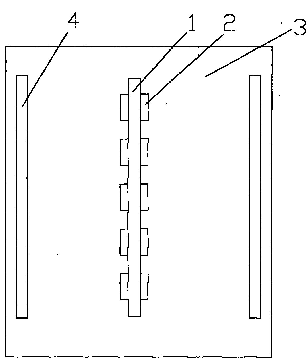
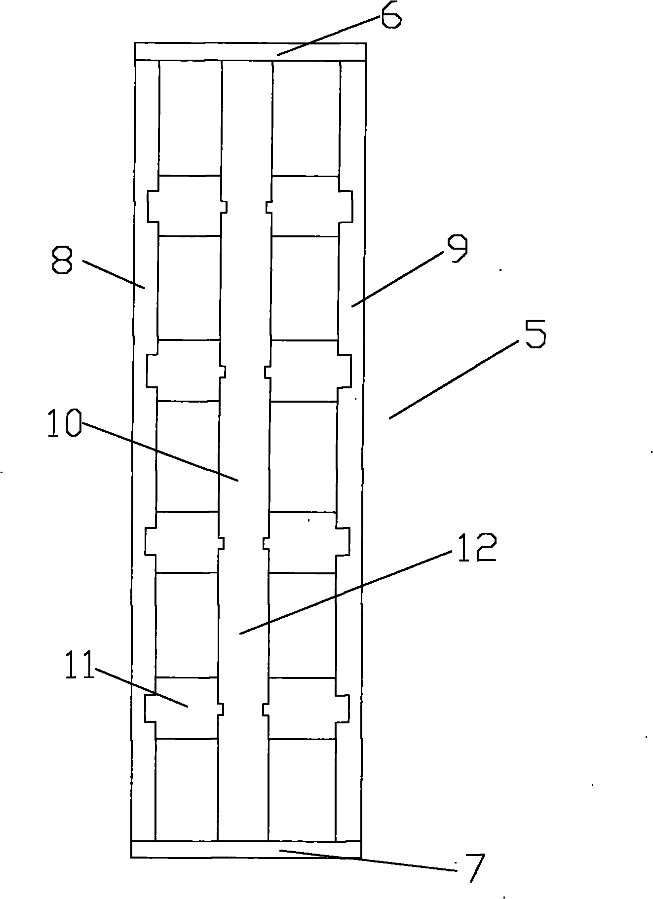
[0015] Such as figure 1 with figure 2 As shown, a floating frame with holes on the sides, the floating frame 5 is placed in the solution of the electroplating tank 3, and the top of the floating frame 5 is provided with a hanger 1 connected to the negative pole of the power supply. The wall is respectively provided with a number of chucks for clamping the plated parts 2, and the clamped plated parts 2 are located under the hanger 1, and a lifting device for controlling the lifting of the hanger 1 is arranged at the front and rear ends of the hanger 1. In the electroplating tank 3, the two sides of the hanger 1 are respectively provided with plating metal 4 connected to the positive pole of the power supply. Such as image 3 As shown, the floating frame 5 is composed of a front fixed plate 6, a rear fixed plate 7, a left anode baffle 8, a right anode baffle 9 and a ...


PUM


Abstract

The invention discloses a scaffold which is arranged in an electroplating bath and provided with a hole on a side edge. The scaffold is arranged in the solution of the electroplating bath; coated metal connected with the anode of a power supply is arranged in the electroplating bath; the top of the scaffold is provided with a rack connected with the cathode of the power supply; the rack is provided with a plurality of collets for clamping a plated part; the clamped plated part is positioned below the rack; and the front and back ends of the rack are provided with elevating devices for controlling the rack to ascend and descend. The scaffold is characterized in that: the scaffold consists of a front fixing plate, a back fixing plate, a left anode baffle plate, a right anode baffle plate and a middle beam; the middle beam is arranged between the middle part of the front fixing plate and the middle part of the back fixing plate; and the upper parts of the left anode baffle plate and the right anode baffle plate are provided with through holes respectively. The problems of non-uniform thicknesses of clad layers at the bottom of the plated part and at other positions of the plated part and the ununiformity of the whole clad layers in the prior art are solved and the scaffold with the hole on the side edge which has a simple structure and can improve the uniformity of the clad layers is provided.

Description

technical field [0001] The invention relates to the technical field of electroplating equipment, in particular to a floating rack arranged in an electroplating tank with holes on its side. Background technique [0002] Electroplating is the process of plating a thin layer of other metals or alloys on the surface of certain metals using the principle of electrolysis. It is a process of using electrolysis to attach a layer of metal film to the surface of metal or other material parts to prevent corrosion and improve Abrasion resistance, conductivity, light reflection and aesthetic enhancement. During electroplating, the plated metal is connected to the anode, and the plated piece is connected to the cathode. The cathode and anode are connected by the electrolyte solution of the plated metal ions, and the plated piece must be immersed in the electrolyte solution. Since the depth of the anode in the electroplating tank is deeper than the depth of the cathode, the current genera...

Claims


Application Information

Patent Timeline
IPC IPC(8): C25D17/06
Inventor 韩业刚徐守杰
Owner 昆山元茂电子科技有限公司
Why Eureka
Eureka Blog
Learn More