Stabilized-pressure oil supply system of high-pressure direct-injection injector and control method thereof

A fuel supply system and fuel injector technology, applied in the directions of fuel injection control, electrical control, charging system, etc., can solve problems such as energy waste, preparation difficulties, and difficulty in sealing between fuel injectors and high-pressure fuel rails, and improve safety. performance, reducing oil pressure fluctuations

Inactive Publication Date: 2011-02-02
BEIHANG UNIV
View PDF4 Cites 18 Cited by
  • Summary
  • Abstract
  • Description
  • Claims
  • Application Information

AI Technical Summary

Problems solved by technology

[0003] However, when conducting high-pressure direct-injection engine fuel injector experiments, the fuel injectors must be tested under different fuel injection pressures. The design and manufacture of the high-pressure oil pump camshaft drive system and the fuel quantity control electronic control drive mechanism are very complicated. Difficult; and because a single experiment only needs to test a single injector of a certain type, while the normal fuel rail supplies oil to multiple injectors and is connected to multiple injectors at the same time, so the injector and It is also difficult to achieve a reliable seal between high-pressure fuel rails, such as reference 2: Mao Liwei, Research on the spray characteristics of porous injectors for direct-injection gasoline engines. Master's thesis of Tianjin University, 2008, which records the use of three-phase asynchronous motors Drive the in-line two-cylinder oil pump to pump oil for the high-pressure oil rail. During the experiment, the control of the oil rail pressure is complicated. The structure of the drive system of the high-pressure oil pump is complex, and the installation and production requirements are high. Continuous work supplies oil to the high-pressure oil rail, which not only wastes energy, but also causes noise pollution to the laboratory
In addition, since the high-pressure oil rail is used for steady-pressure oil supply, there is the above-mentioned problem of sealing between the oil rail and the injector

Method used


Image

  • Stabilized-pressure oil supply system of high-pressure direct-injection injector and control method thereof
  • Stabilized-pressure oil supply system of high-pressure direct-injection injector and control method thereof

Examples


Embodiment Construction

[0039] The present invention will be described in detail below in conjunction with the accompanying drawings.

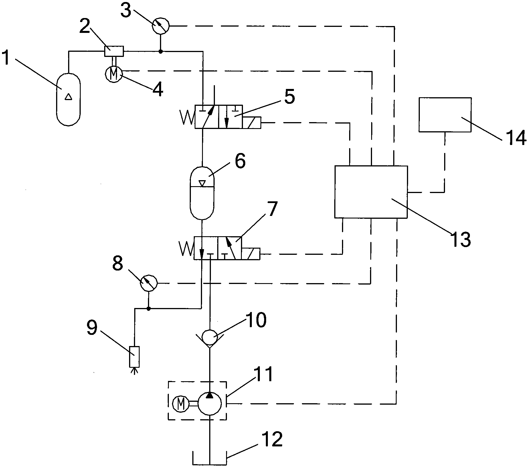
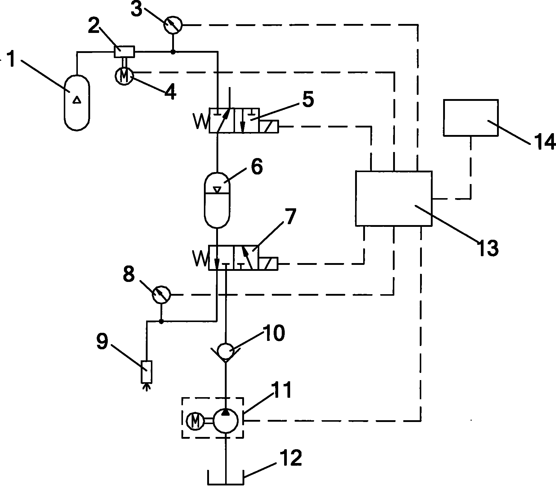
[0040] The stabilized oil supply system of the high-pressure direct injection fuel injector provided by the present invention, such as figure 1As shown, it mainly includes: high-pressure nitrogen cylinder 1, pressure reducer 2, stepping motor 4, pressure sensor A3, two-position three-way solenoid valve A5, accumulator 6, two-position three-way solenoid valve B7, pressure sensor B8, Fuel injector 9, check valve 10, fuel pump 11, fuel tank 12, controller 13 and display screen 14.

[0041] The high-pressure nitrogen cylinder 1 is used to inflate the accumulator 6, and the high-pressure nitrogen cylinder 1 and the accumulator 6 are sequentially connected with a pressure reducer 2 and a two-position three-way solenoid valve A5 through a pipeline to form a gas passage; The other end of the accumulator 6 is connected to the inlet of the two-position three-way solenoid valv...


PUM


Abstract

The invention provides a stabilized-pressure oil supply system of a high-pressure direct-injection injector and a control method thereof. The stabilized-pressure oil supply system mainly comprises a high-pressure nitrogen cylinder, a pressure reducer, a step motor, a pressure sensor A, a two-position three-way electromagnetic valve A, an accumulator, a two-position three-way electromagnetic valve B, a pressure sensor B, an injector, a check valve, a fuel pump, an oil tank, a controller and a display screen. The stabilized-pressure oil supply system can automatically regulate the injection pressure of the injector of the stabilized-pressure oil supply system to a set injection pressure through the controller of the stabilized-pressure oil supply system according to the pressure parameter set on the display screen and can reduce the oil pressure fluctuation in the injection of the injector. The stabilized-pressure oil supply system has an accumulator oil supply path, so the fuel supply to the accumulator can be realized without detaching the pipe.

Description

technical field [0001] The invention belongs to the technical field of high-pressure direct-injection engines, and in particular relates to a stabilized-pressure fuel supply system and a control method for high-pressure direct-injection fuel injectors. Background technique [0002] For high-pressure direct-injection engines, the fuel injection pressure is up to 20MPa or more, and the fuel supply system mostly uses the engine's camshaft to drive the high-pressure oil pump to pump oil to the high-pressure fuel rail, and supplies fuel to each injector of the engine through the high-pressure fuel rail. Among them, the structure of the high-pressure oil pump and the camshaft is complicated, not only the cost is high, but also the installation and fixing requirements are high, and a set of electronic control drive mechanism is required to accurately control the oil supply of the high-pressure oil pump, such as Reference 1: Hu Linfeng, Ge Fei , Huang Jian. Structural characteristic...

Claims


Application Information

Patent Timeline
Patent Type & Authority Applications(China)
IPC IPC(8): F02D41/38F02M65/00
Inventor 杨世春郭斌李明徐斌崔海港曹耀光陈铁
Owner BEIHANG UNIV
Why Eureka
Try Eureka