
Chemical mechanical lapping method

A grinding method and chemical mechanical technology, which is applied in the direction of grinding devices, grinding machine tools, electrical components, etc., can solve the problems of reducing the stability of devices and small metal resistance, and achieve the effect of improving stability

Active Publication Date: 2012-11-28
SEMICON MFG INT (SHANGHAI) CORP +1
View PDF0 Cites 0 Cited by
  • Summary
  • Abstract
  • Description
  • Claims
  • Application Information

AI Technical Summary

Problems solved by technology

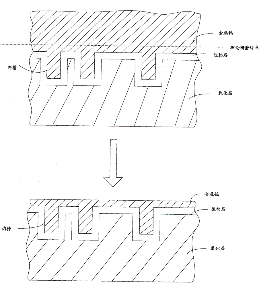
[0007] In an ideal situation, when the first process ends, the grinding end point is just slightly higher than the theoretical grinding end point, that is to say, in an ideal case, when the second process is executed from a position slightly higher than the grinding end point, it must be able to detect To the end of theoretical grinding, however, in practical applications, due to process errors, it is difficult to make the thickness of the metal layer deposited on each wafer be the ideal thickness, and there will be certain differences in metal hardness, etc., and the grinding machine The MRR of the stage will also have a certain difference. When the deposited metal layer is thin, the hardness is small, or the MRR is large, since the execution time of the first process is set to a fixed value, when the first process ends, there is It may be that the upper surface of the metal layer has been lower than the theoretical grinding end point. In this case, when the second process is performed, the theoretical grinding end point cannot be detected. In practical applications, when the theoretical grinding end point cannot be detected in the second process At the end, the second process is executed according to the preset maximum value, so when the first process and the second process are completed, the entire oxide layer and the metal in the trench have been over-polished, and the thickness of the entire oxide layer is smaller than ideal. The thickness of the oxide layer below is small, and the metal filled in the trench is also less than the ideal metal, resulting in a smaller metal resistance than the ideal metal resistance, which reduces the stability of the device.

Method used


Image

  • Chemical mechanical lapping method
  • Chemical mechanical lapping method
  • Chemical mechanical lapping method

Examples


Embodiment Construction

[0018] In order to make the object, technical solution, and advantages of the present invention clearer, the present invention will be further described in detail below with reference to the accompanying drawings and examples.

[0019] The core idea of ​​the present invention is: when performing the first process, detect the theoretical grinding end point in real time, when the theoretical grinding end point is detected, end the first process and execute the second process, which can ensure that when the metal layer is ground to a point close to the theoretical The second process is performed immediately when the position of the end point is ground, and after the first process and the second process are completed, the entire oxide layer and the metal in the trench can be prevented from being over-grinded.

[0020] Figure 4 It is a flowchart of an embodiment of a chemical mechanical polishing method provided by the present invention. Such as Figure 4 As shown, the method in...


PUM


Abstract

The invention discloses a chemical mechanical lapping method which comprises the following steps: when carrying out lapping on metals, detecting a theoretic lapping end point in real time, and when the theoretic lapping end point is detected, lapping the surplus metals outside a blocking layer, an oxidation layer and a groove; and continuing to carry out lapping on the oxidation layer, wherein the lapping time of the oxidation layer is a preset fixed value. By using the method, the stability of devices can be improved.

Description

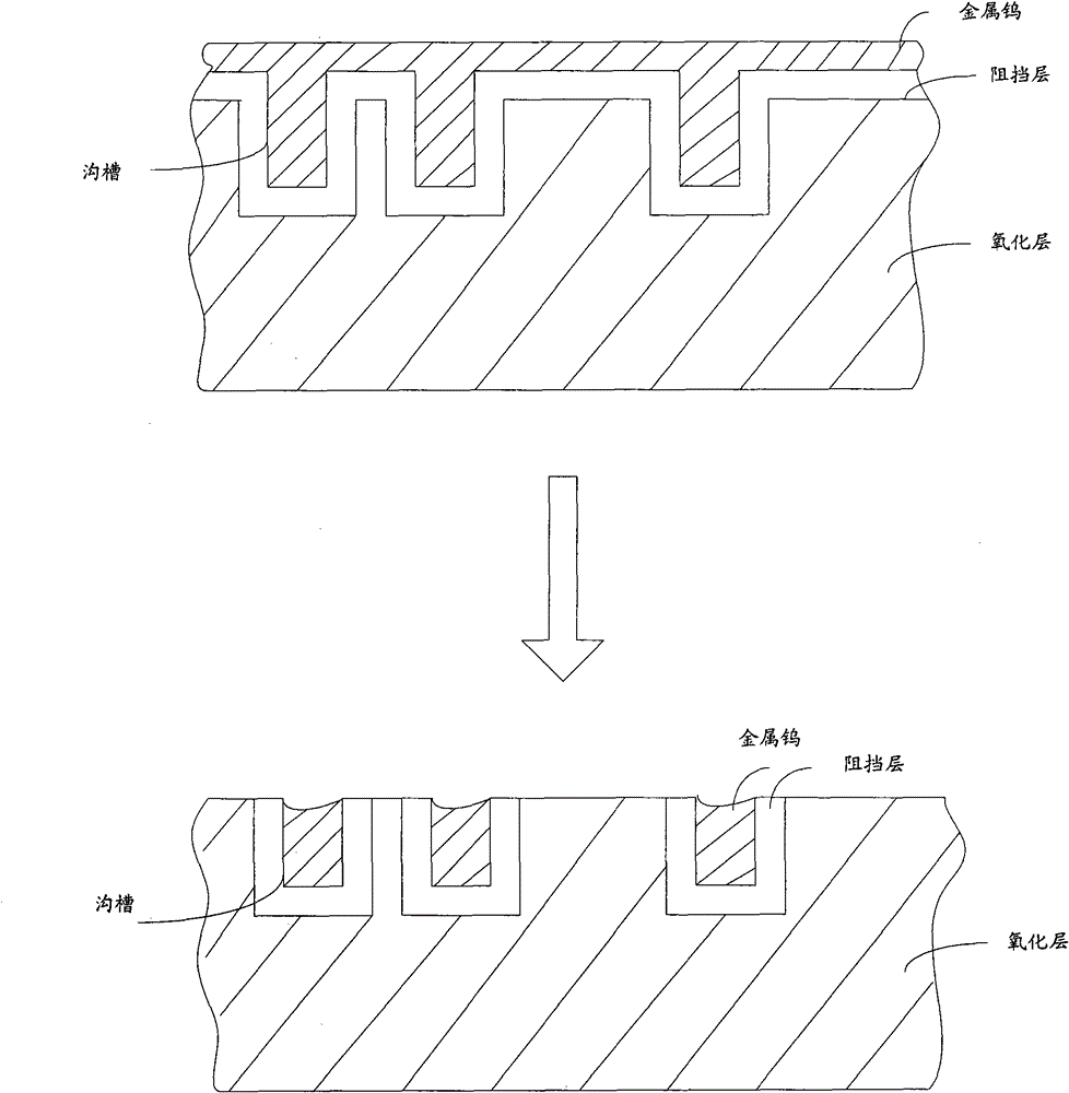
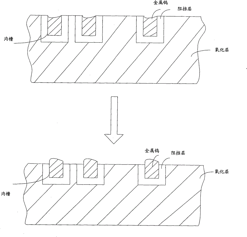
technical field [0001] The invention relates to the field of semiconductor manufacturing, in particular to a chemical mechanical grinding method. Background technique [0002] At present, with the wide application of electronic devices, the manufacturing process of semiconductors has been developed rapidly. In the manufacturing process of semiconductors, a chemical mechanical polishing process (CMP) is involved. CMP is mainly realized by three grinding machines, and each grinding machine performs a grinding process respectively, and the grinding of metal tungsten is taken as an example to illustrate these three grinding processes respectively. [0003] figure 1 It is a schematic cross-sectional view of the first process of the chemical mechanical polishing method in the prior art. Execute the first process on the first grinding machine table (Platen 1), such as figure 1 As shown, the metal tungsten is ground with a large material removal rate (MMR) to remove most of the m...

Claims


Application Information

Patent Timeline
Patent Type & Authority Patents(China)
IPC IPC(8): H01L21/02H01L21/3105H01L21/321B24B37/013B24B37/00
Inventor 胡宗福
Owner SEMICON MFG INT (SHANGHAI) CORP
Learn More