
Photoetching method

A technology of lithography and exposure parameters, applied in microlithography exposure equipment, optics, optomechanical equipment, etc., can solve the problems of over-grinding and insufficient grinding of the wafer area, and achieve the effect of improving the yield rate

Pending Publication Date: 2022-06-28
HUA HONG SEMICON WUXI LTD +1
View PDF0 Cites 0 Cited by
  • Summary
  • Abstract
  • Description
  • Claims
  • Application Information

AI Technical Summary

Problems solved by technology

[0004] This application provides a photolithography method, which can solve the problem that some areas on the wafer are over-polished or insufficiently ground due to the load effect on the surface of the wafer when the surface of the wafer is chemically mechanically polished

Method used


Image

  • Photoetching method

Examples


Embodiment Construction

[0022] The technical solutions in the present application will be clearly and completely described below with reference to the accompanying drawings. Obviously, the described embodiments are a part of the embodiments of the present application, but not all of the embodiments. Based on the embodiments in the present application, all other embodiments obtained by those of ordinary skill in the art without creative work fall within the protection scope of the present application.

[0023] In the description of this application, it should be noted that the terms "center", "upper", "lower", "left", "right", "vertical", "horizontal", "inner", "outer", etc. The indicated orientation or positional relationship is based on the orientation or positional relationship shown in the accompanying drawings, which is only for the convenience of describing the present application and simplifying the description, rather than indicating or implying that the indicated device or element must have a ...


PUM


Abstract

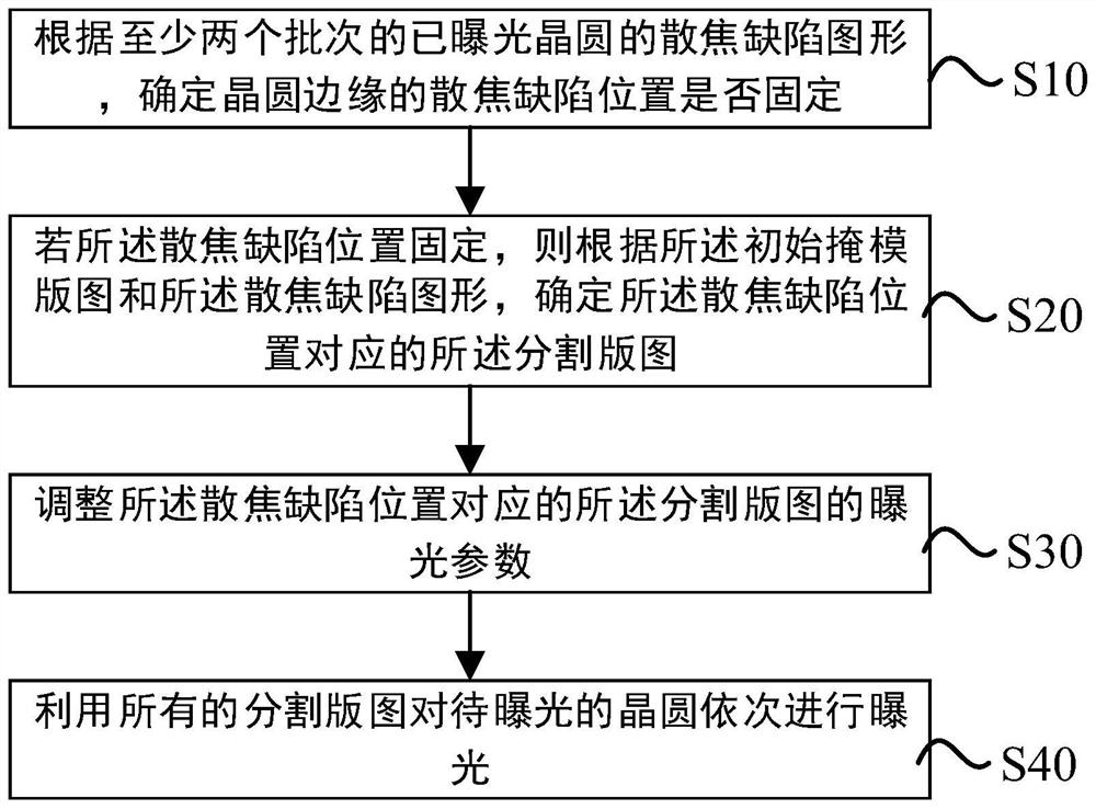
The photoetching method comprises the following steps: determining whether the position of a defocusing defect on the surface of a wafer is fixed or not according to a defocusing defect pattern; if the position of the defocusing defect is fixed, determining a segmentation layout corresponding to the position of the defocusing defect according to the initial mask plate graph and the defocusing defect graph; adjusting exposure parameters of the segmented layout corresponding to the defocusing defect position; and sequentially exposing the wafer by using all the segmentation layouts. According to the method, the position of the defocus defect is fixed, and the segmentation layout corresponding to the position of the defocus defect is determined by using the initial mask plate graph and the defocus defect graph, so that the exposure parameter of the segmentation layout corresponding to the position of the defocus defect is adjusted; therefore, the position of the mask pattern transferred to the wafer is adjusted in advance in the photoetching process, the problem that a partial region on the wafer is over-ground or insufficiently ground due to a load effect generated on the surface of the wafer when the surface of the wafer is chemically and mechanically ground is avoided, and the yield of a device is improved.

Description

technical field [0001] The present application relates to the technical field of semiconductor lithography, and in particular, to a lithography method. Background technique [0002] Currently, chemical mechanical polishing (CMP) processes are widely used in various stages of improving wafer flatness. [0003] In the early stage of the manufacturing process of the integrated circuit chip, it is necessary to design the graphics of the integrated circuit chip. Different graphics can be designed through the layout, and the graphics density of different graphics will be different. In the later manufacturing process, due to the characteristics of the CMP process, areas with different pattern densities on the wafer are prone to loading effects, resulting in over-grinding or under-grinding in local areas of the wafer surface, thus affecting the final preparation. performance of radio frequency chips (semiconductor chips). SUMMARY OF THE INVENTION [0004] The present application...

Claims


Application Information

Patent Timeline
IPC IPC(8): G03F7/20
CPCG03F7/70475G03F7/70433
Inventor 董俊张其学陈骆王雷
Owner HUA HONG SEMICON WUXI LTD
Learn More