
High-grade highway structure of soaked sand dredger filling embankment in coastal region

A high-grade dredging sand filling technology, applied in roads, roads, buildings, etc., can solve the problems of high cost, long cycle, poor stability, etc., achieve the effect of reducing direct investment, improving comprehensive road performance, and reducing project cost

Inactive Publication Date: 2011-02-09
唐山市滨海大道建设指挥部
View PDF3 Cites 7 Cited by
  • Summary
  • Abstract
  • Description
  • Claims
  • Application Information

AI Technical Summary

Problems solved by technology

[0003] In the above-mentioned highway construction projects, the subgrade materials of the road bed are generally replaced and filled with foreign mountain stones or mountain soil. Although the stability and corrosion resistance of the roadbed can be greatly improved, due to the mountain stones or Mountain soil resources are scarce and need to be transported from far away mountainous areas, so the cost is high and the cycle is long, which cannot meet the requirements of the project
Therefore, there are also some projects where local materials are used, and a large amount of dredged sand is used as roadbed filler, but its road engineering characteristics are greatly affected by seawater, and its stability is poor. The design of graded highway structure is of great significance and value for the design, construction and long-term operation safety of this new type of highway structure

Method used


Image

  • High-grade highway structure of soaked sand dredger filling embankment in coastal region
  • High-grade highway structure of soaked sand dredger filling embankment in coastal region

Examples


Embodiment Construction

[0012] The specific technical characteristics are as follows:

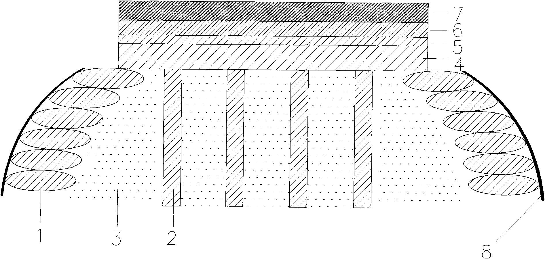
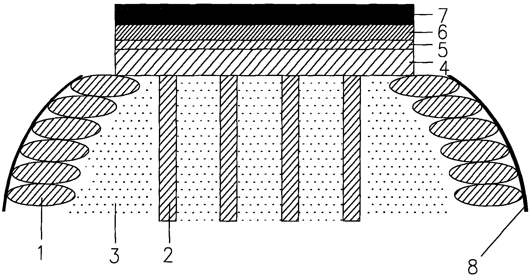
[0013] 1. The bagged sand cofferdam 1, the anti-seepage protective layer outside the cofferdam 8, the dredged sand inside the cofferdam 3, the pile foundation in the dredged sand 2, the mountain stone layer 4, the solidified mud sand layer 5, cement The stable crushed stone layer 6 and the asphalt concrete layer 7 are formed.

[0014] 2. The bagged sand cofferdam 1 is built on both sides of the road bed, and waterproof and moisture-proof measures such as anti-seepage geotextile, molded bag concrete and embankment stone slope protection are adopted outside the cofferdam 8 .

[0015] 3. The height of the cofferdam is marked as the top surface of the lower road bed; the interior of the cofferdam uses dredging sand 3, the maximum particle size of the dredged sand is required to be less than 0.5mm, and the mud content is not more than 10%. The height of the cofferdam is equal to or not less than 0.5 meters.

[0016] ...


PUM

PropertyMeasurementUnit
Thicknessaaaaaaaaaa
Particle sizeaaaaaaaaaa

Abstract

The invention relates to a high-grade highway structure of a soaked sand dredger filling embankment in a coastal region, relating to an embankment pavement structure of a novel highway. The highway structure comprises a bagged sand cofferdam (1), an anti-leakage protection layer (8) outside the cofferdam (1), dredger filled sand (3) in the cofferdam, a pile base (2) in the dredger filled sand, a crushed rock layer (4), a cement-straightening gravel layer (6) and an asphalt cement layer (7) and is characterized in that a solidified cement layer is paved between the crushed rock layer (4) and the cement-straightening gravel layer (6), the crushed rock layer (4) has the thickness of 20-80 cm, the solidified cement layer with the thickness of 40-80 cm is paved at the top of the crushed rock layer (4), the cement-straightening gravel layer with the thickness of 30-60 cm is arranged on the solidified cement layer, and the total thickness of the three layers is 100-160 cm. According to the invention, great mounts of dredger filled sand and silt abundant in the coastal region are used as building materials for roadbeds and embankments and substitute a great amount of crushed rock needing long-distance transportation and having higher cost so as to decrease the construction cost and improve the comprehensive road performance; and the direct investment of the road construction is reduced by 20-40 percent by substituting partial cement for stabilizing gravels.

Description

technical field [0001] The patent of the invention relates to the subgrade pavement structure of a new type of highway, especially a high-grade highway suitable for flooding in coastal areas built with dredged sand and silt, which are rich in resources in coastal areas, as roadbed and subgrade materials. Background technique [0002] my country has formed a large number of land reclamation projects by using dredging sand filling methods. For example, Tangshan Caofeidian will become the world's largest reclamation project with a single dredging reclamation area. By 2020, the Caofeidian Industrial Zone will eventually be reclamated by sea reclamation. It forms a land area with a radius of 310 square kilometers. In the above-mentioned land reclamation projects, road construction is the most important infrastructure, and its economy, durability and practicality are the keys to restrict the development of the whole region. At present, many roads in land reclamation projects are b...

Claims


Application Information

Patent Timeline
IPC IPC(8): E01C3/00
Inventor 张务民潘凤文王立伟聂宁柳永年李庆国崔树国韩金华何亚楼葛新春丁峰赵百杰
Owner 唐山市滨海大道建设指挥部
Learn More