Device for measuring pressure, variation in acoustic pressure, a magnetic field, acceleration, vibration, or the composition of a gas

A gas composition, magnetic field technology, applied in the fields of acceleration, vibration or gas composition, magnetic field, pressure measurement, sound pressure change, and can solve problems such as diaphragm adhesion, complex structure, movement, etc.

Active Publication Date: 2011-02-09
VALTION TEKNILLINEN
View PDF9 Cites 19 Cited by
  • Summary
  • Abstract
  • Description
  • Claims
  • Application Information

AI Technical Summary

Problems solved by technology

Since the diaphragms are very close to each other, this leads to several problems: adhesion of the diaphragms to each other, movement due to thermal expansion of the substrate and com

Method used


Image

  • Device for measuring pressure, variation in acoustic pressure, a magnetic field, acceleration, vibration, or the composition of a gas
  • Device for measuring pressure, variation in acoustic pressure, a magnetic field, acceleration, vibration, or the composition of a gas
  • Device for measuring pressure, variation in acoustic pressure, a magnetic field, acceleration, vibration, or the composition of a gas

Examples


Embodiment Construction

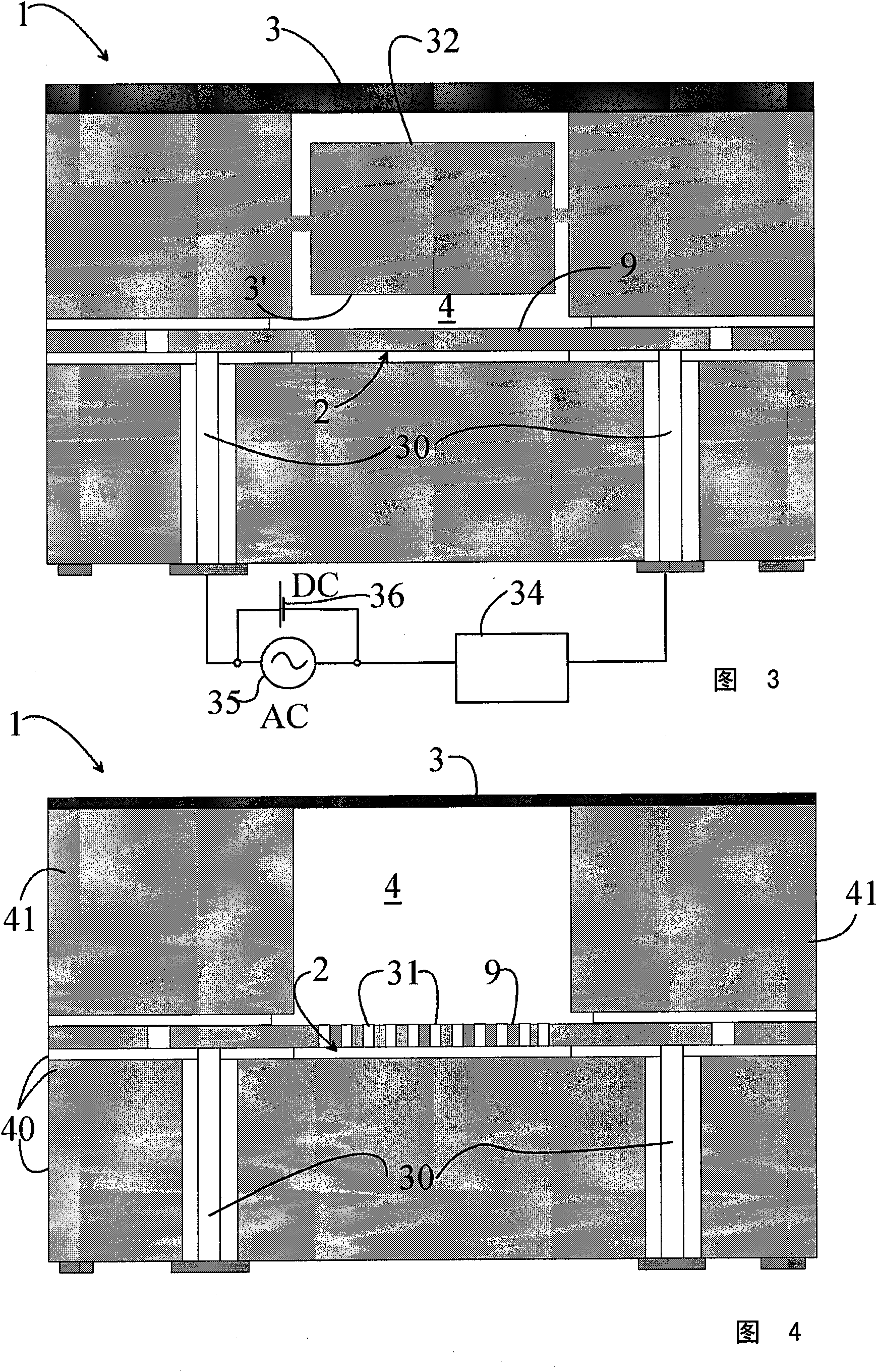
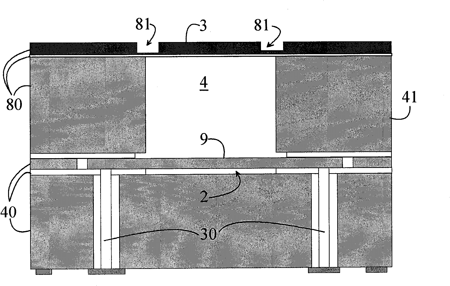
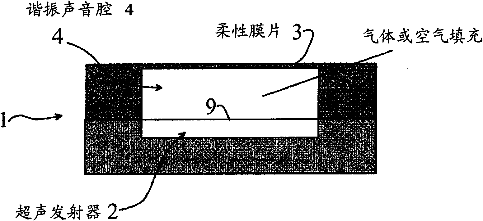
[0025] Figure 1a with Figure 1b A schematic construction of an ultrasonic sensor 1 according to the invention is shown. exist Figure 1a A configuration in which the ultrasonic transmitter 2 is formed by a single cavity is shown in and in Figure 1b The case of sound formation using several parallel oscillating emitters 2 is shown in . The diaphragm 9 of the transmitter 2 creates a resonant ultrasound in the cavity 4 above it. The ultrasound transmitter 2 generates electrical series and parallel resonances. The impedance of a series resonance is typically 1 to 10 kΩ and that of a parallel resonance is 10 to 100 times greater, always according to the quality factor of the resonator. It can be assumed that the flexible upper diaphragm 3 will reflect most of the sound back and only a small part will radiate out behind the diaphragm 3 . In practice, this means that the impedance of the series resonance is reduced. If the diaphragm radiates power outwards, the quality factor...


PUM


Abstract

The invention relates to a sensor (1) and a method for measuring pressure, variation in sound pressure, a magnetic field, acceleration, vibration, or the composition of a gas. The sensor (1) comprises an ultrasound transmitter (2), and a cavity (4) arranged in connection with it. According to the invention, the sensor (1) comprises a passive sensor element (3, 3') located at the opposite end of the cavity (4) to the ultrasound transmitter (2), the distance of which from the ultrasound transmitter (2) is selected in such a way that the resonance condition is met at the ultrasound frequency used, the ultrasound transmitter (2) comprises a light-construction diaphragm oscillator (9), which is thus well connected to the surrounding medium, and the sensor includes means for measuring the interaction between the ultrasound transmitter (2) and the cavity (4).

Description

technical field [0001] The invention relates to a device for measuring pressure, sound pressure change, magnetic field, acceleration, vibration or gas composition according to the preamble of claim 1 . [0002] The invention also relates to methods for measuring pressure, sound pressure changes, magnetic fields, accelerations, vibrations or gas composition. Background technique [0003] In micromechanical pressure sensors, microphones, etc., the distance between two diaphragms is measured capacitively. This can be done by measuring the voltage caused by movement, or by measuring the capacitance at high frequencies. Since the membranes are very close to each other, this leads to several problems: the membranes stick to each other, movement due to thermal expansion of the substrate and components, etc. In addition to the mechanical problems, the current construction is faced with the fact that the impedance between the two diaphragms is high and all leakage currents cause pr...

Claims


Application Information

Patent Timeline
IPC IPC(8): G01L9/00B81B7/02G01H15/00B81B3/00
CPCG01P15/08G01H9/008G01N2291/048G01N29/036G01L11/06G01P15/18G01N29/222G01N2291/0215B81B3/0018B81B7/02G01H15/00
Inventor H·塞帕T·西兰帕
Owner VALTION TEKNILLINEN
Why Eureka
Try Eureka