
End cap voltage control of ion traps

An ion trap and end cap electrode technology is applied in the field of ion trap and ion trap mass spectrometer, which can solve the problems of increasing the size, weight, and power consumption of the mass spectrometer system.

Inactive Publication Date: 2011-02-09
1ST DETECT CORP
View PDF3 Cites 5 Cited by
  • Summary
  • Abstract
  • Description
  • Claims
  • Application Information

AI Technical Summary

Problems solved by technology

These additional electronics increase the size, weight, and power consumption of the mass spectrometer system

Method used


Image

  • End cap voltage control of ion traps
  • End cap voltage control of ion traps
  • End cap voltage control of ion traps

Examples


Embodiment Construction

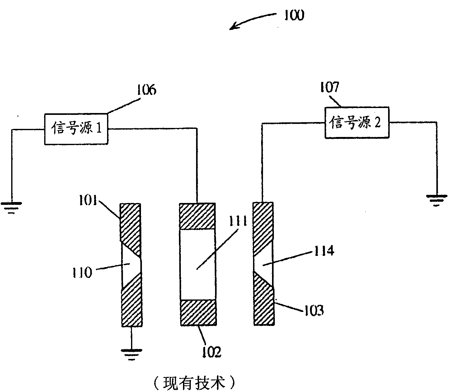
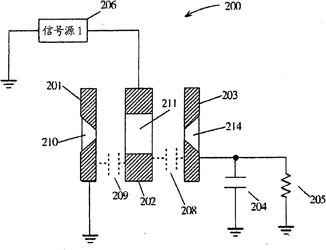
[0024] Embodiments herein provide electrical actuation for the end caps of an ion trap to improve ion trap operation. Embodiments provide simple circuitry that derives the electrical excitation signal from the signal present on the central electrode of the ion trap.

[0025] In one embodiment, passive electrical components are used to apply a signal to the second end cap of the ion trap to enhance performance. An added component is used to apply a portion of the central electrode excitation signal to the second end cap. This results in axial excitation within the ion trap, which improves performance with negligible power loss, minimal complexity, and with minimal impact on system size. In some embodiments, the added components may result in an increase in the impedance seen at the central electrode due to the circuit configuration of the added components, which results in a substantial reduction in overall system power consumption.

[0026] In an embodiment, the frequency of...


PUM


Abstract

An ion trap for a mass spectrometer has a conductive central electrode with an aperture extending from a first open end to a second open end. A conductive first electrode end cap is disposed proximate to the first open end thereby forming a first intrinsic capacitance between the first end cap and the central electrode. A conductive second electrode end cap is disposed proximate to the second open end thereby forming a second intrinsic capacitance between the second end cap and the central electrode. A first circuit couples the second end cap to a reference potential. A signal source generating an AC trap signal is coupled to the central electrode. An excitation signal is impressed on the second end cap in response to a voltage division of the trap signal by the first intrinsic capacitance and the first circuit.

Description

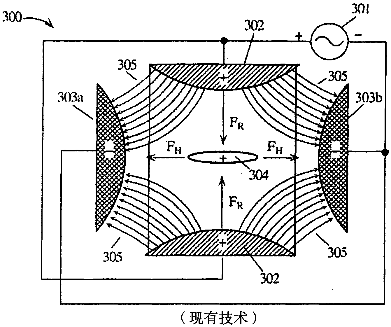
[0001] Cross References to Related Applications [0002] This application claims priority to US Provisional Application Serial No. 61 / 012,660, filed December 10, 2007, which is hereby incorporated by reference. technical field [0003] The present invention relates to ion traps, ion trap mass spectrometers, and more particularly, to control signal generation for ion traps used in mass spectrochemical analysis. Background technique [0004] Using an ion trap is one way to perform mass spectrometric chemical analysis. Ion traps dynamically capture ions from a measurement sample using a dynamic electric field generated by one or more drive signals. Ions are selectively ejected corresponding to their mass-to-charge ratio (mass(m) / charge(z)) by varying the characteristics (eg, amplitude, frequency, etc.) of the electric field that traps the ions. More background information on ion trap mass spectrometry can be found in "Practical Aspects of Ion Trap Mass Spectrometry" by Raymon...

Claims


Application Information

Patent Timeline
Patent Type & Authority Applications(China)
IPC IPC(8): H01J49/00
CPCH01J49/424H01J49/26
Inventor 戴维·拉弗蒂
Owner 1ST DETECT CORP
Learn More