Six-degree-of-freedom cervical-vertebra grinding parallel robot

A degree of freedom, robotic technology, used in medical science, surgery, etc., can solve the problems of high workload, insufficient precision, and excessive radiation for doctors, and achieve the effects of compact structure, improved precision and quality, and reduced radiation dose.

Inactive Publication Date: 2011-02-16
HARBIN INST OF TECH
View PDF4 Cites 21 Cited by
  • Summary
  • Abstract
  • Description
  • Claims
  • Application Information

AI Technical Summary

Problems solved by technology

[0003] The purpose of the present invention is to solve the problems of insufficient accuracy, excessive radiation, and high work intensity of doctors in the existing artificial cervical disc replacement surgery, and to provide a six-degree-of-freedom cervical vertebra grinding parallel robot

Method used


Image

  • Six-degree-of-freedom cervical-vertebra grinding parallel robot
  • Six-degree-of-freedom cervical-vertebra grinding parallel robot
  • Six-degree-of-freedom cervical-vertebra grinding parallel robot

Examples


specific Embodiment approach 1

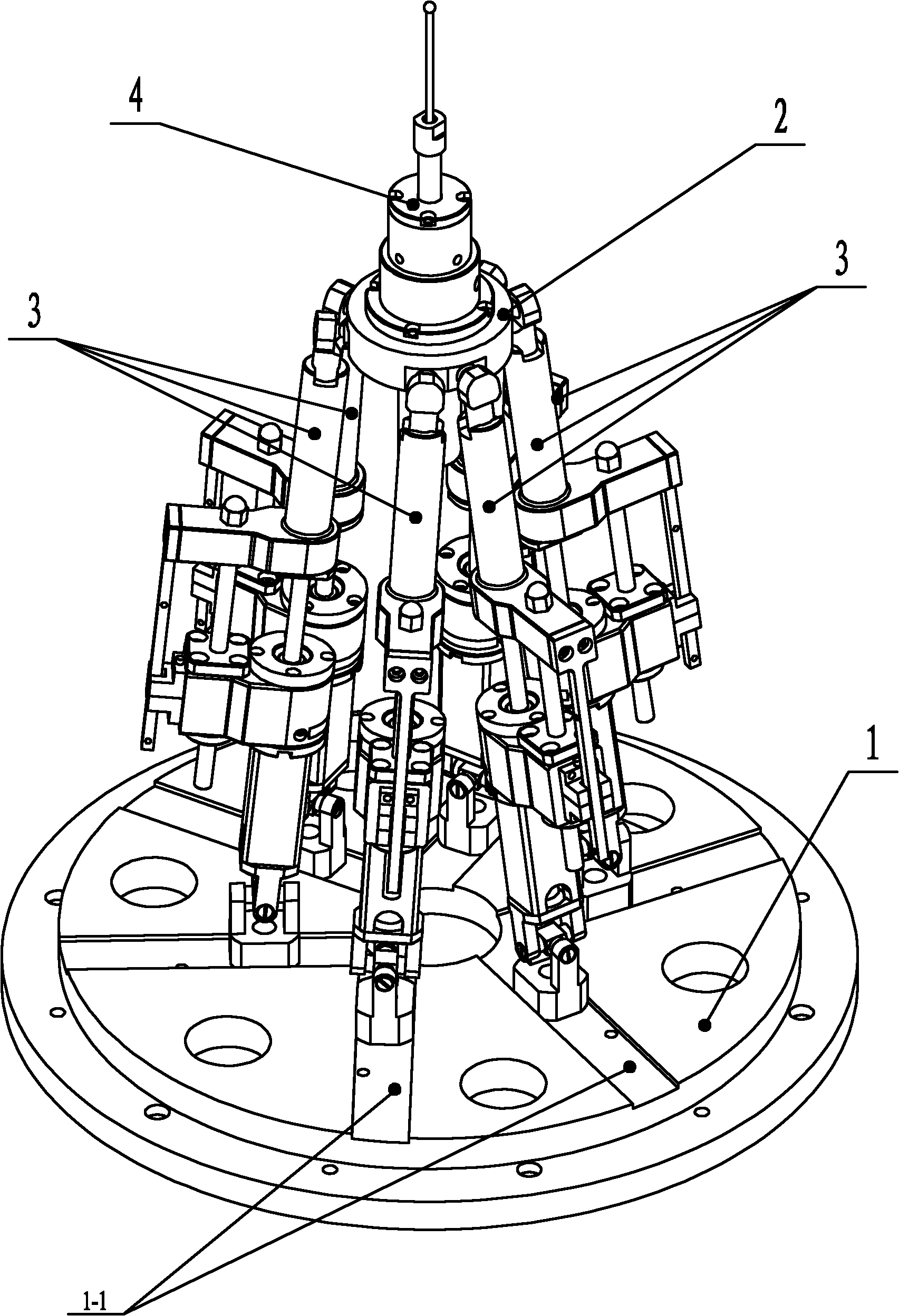
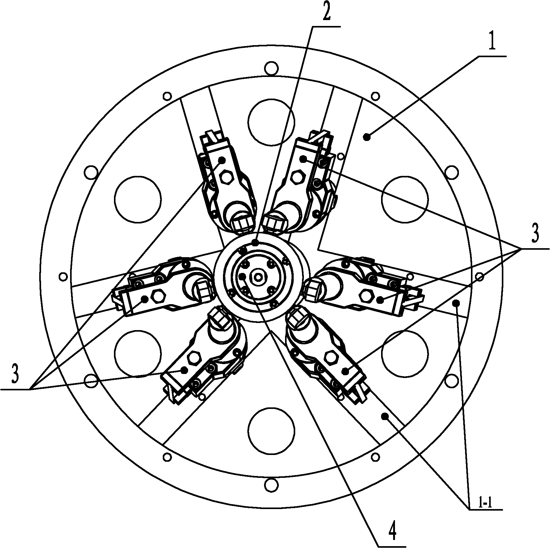
[0007] Specific implementation mode one: combine Figure 1-Figure 3 , Figure 5 , Figure 7 or Figure 8 , Figure 9 Describe this embodiment. The six-degree-of-freedom cervical vertebra grinding parallel robot in this embodiment includes a fixed platform 1, a moving platform 2, a grinding drill 4 and three pairs of branch chains. The fixed platform 1 and the moving platform 2 are connected by three pairs of branch chains. connection, each pair of branch chains includes two branch chains 3, and each branch chain 3 includes a ball hinge mechanism 3-1, a ball screw linear drive mechanism and a Hooke hinge mechanism 3-12, and the ball hinge mechanism 3-1 is arranged on the ball screw The upper end of the rod linear drive mechanism, the Hooke hinge mechanism 3-12 is arranged at the lower end of the ball screw linear drive mechanism, the ball hinge mechanism 3-1 is connected with the moving platform 2, the Hooke hinge mechanism 3-12 is connected with the fixed platform 1, and th...

specific Embodiment approach 2

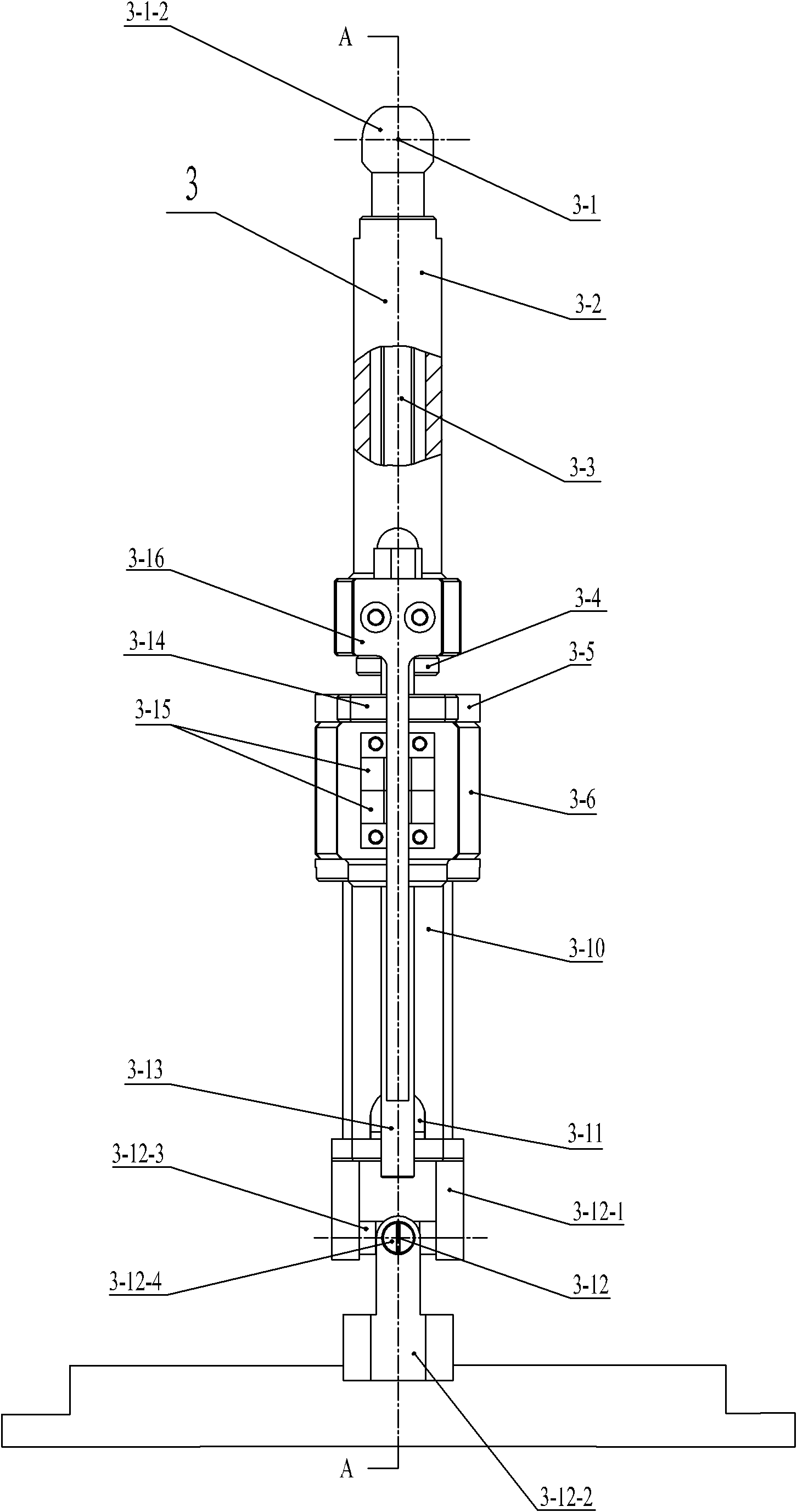
[0009] Specific implementation mode two: combination Figure 3-Figure 6 Describe this embodiment, the ball screw linear drive mechanism of this embodiment includes a branch chain front telescopic rod 3-2, a ball screw 3-3, a ball nut 3-4, a bearing end cover 3-5, and a branch chain motor connecting body 3 -6, Bearing Spacer 3-7, Lock Nut 3-8, Branch Chain Rear Rod 3-10, Branch Chain Motor 3-11, Hooke Hinge 3-12, Round Guide Rail 3-13, Linear Ball Guide Bushing 3-14 , two sensors 3-15, positioning block 3-16, two second bearings 3-18, the branch chain motor connection body 3-6 includes the first connection chamber 3-6-1 and is parallel to the first connection chamber and The second connection cavity 3-6-2 is offset by a certain distance, one end of the ball screw 3-3 is installed in the front expansion rod 3-2 of the branch chain, and one end of the ball screw 3-3 is installed in the ball nut 3-4 , the ball nut 3-4 is fixedly connected on the front expansion rod 3-2 of the bra...

specific Embodiment approach 3

[0010] Specific implementation mode three: combination Figure 5 Describe the present embodiment, the ball screw linear drive mechanism of the present embodiment also includes jackscrew cover 3-9 and jackscrew 3-17, is provided with jackscrew hole on branch chain motor connecting body 3-6, and jackscrew cover 3- 9 is arranged on the jacking screw hole, and the input end of the ball screw 3-3 is connected with the output shaft end of the branch chain motor 3-11 through the jacking screw 3-17. Such setting facilitates the installation of the top wire 3-18, and facilitates the replacement and tightening of the top wire 3-18. Other components and connections are the same as those in the second embodiment.


PUM


Abstract

The invention relates to a six-degree-of-freedom cervical-vertebra grinding parallel robot which relates to a grinding parallel robot. The invention aims to solve the problems of insufficient precision, overmuch radiation and large doctor working strength of a traditional manual cervical intervertebral-disc replacement operation. A fixed platform and a movable platform are connected through three pairs of branched chains, a spherical hinge mechanism is arranged at the upper end of a ball-screw linear driving mechanism, a hooker hinge mechanism is arranged at the lower end of the ball-screw linear driving mechanism, the spherical hinge mechanism is connected with the movable platform, the hooker hinge mechanism is connected with the fixed platform, an abrasive-drilling motor penetrates the movable platform, the abrasive-drilling motor is fixedly connected with an abrasive-drilling motor connecting body, the abrasive-drilling motor connecting body is fixedly connected with the movable platform, an abrasive-drilling body is fixedly installed on the abrasive-drilling motor connecting body, an abrasive-drilling jackscrew hole is arranged on the abrasive-drilling body, an abrasive-drilling jackscrew hole cover is installed on the abrasive-drilling jackscrew hole, an abrasive-drilling shaft is connected with the abrasive-drilling motor through a shaft coupler, and a cutting head is connected with the abrasive-drilling shaft through a tightening nut. The invention is applicable to the grinding of cervical vertebra.

Description

technical field [0001] The invention relates to a cervical vertebra grinding parallel robot, in particular to a six-degree-of-freedom cervical vertebra grinding parallel robot. Background technique [0002] The biggest difficulty in artificial cervical disc replacement surgery is the need to grind the articular surface of the prosthesis in the correct position to ensure the cooperation between the prosthesis and the human bone. The therapeutic effect depends heavily on the accuracy of the operation. Currently, a clamp system is used for grinding positioning in artificial cervical disc replacement surgery. This traditional mechanical positioning system is based on the observation of limbs and prostheses with the naked eye. The fixture system is widely used for grinding and grinding positioning during surgery. Uncertainty affects the installation accuracy of the prosthesis. In order to improve the accuracy of surgical positioning, doctors often need to use X-ray machines for...

Claims


Application Information

Patent Timeline
Patent Type & Authority Applications(China)
IPC IPC(8): A61B17/00A61B17/16
Inventor 杜志江吴冬梅田和强
Owner HARBIN INST OF TECH
Why Eureka
Try Eureka