Turning positioning fixture for thin-wall rotational parts and clamping method

A technology for positioning fixtures and revolving bodies, applied in positioning devices, manufacturing tools, metal processing machinery parts, etc., can solve the problems of high processing difficulty, loss, and high rejection rate of parts, improve processing accuracy, reduce human errors, and parts deformation. small effect

Active Publication Date: 2011-02-16
BEIJING RES INST OF TELEMETRY
View PDF4 Cites 18 Cited by
  • Summary
  • Abstract
  • Description
  • Claims
  • Application Information

AI Technical Summary

Problems solved by technology

[0002] When processing rotary parts with thin walls, high parallelism and flatness requirements on ordinary machine tools, there are processing defects due to machine tool precision and traditional clamping methods, such as low machine tool precision, multiple clamping during processing, axial The positioning center is not easy to find, direct clamping is easy to cause the thin-walled parts to be deformed by radial force, etc., which makes the processing of parts difficult, the scrap rate is high, and it is difficult to obtain the accuracy required by the design drawings, which not only reduces work efficiency, but also increases Cost of production
Especially for delicate products, it will cause huge losses

Method used


Image

  • Turning positioning fixture for thin-wall rotational parts and clamping method
  • Turning positioning fixture for thin-wall rotational parts and clamping method
  • Turning positioning fixture for thin-wall rotational parts and clamping method

Examples


Embodiment 1

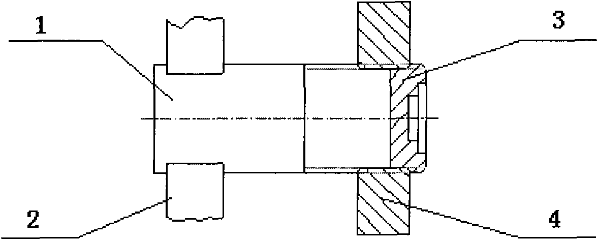
[0032] Such as Figure 4 Shown is the clamping schematic diagram of the first embodiment of the lathe positioning fixture of the present invention. This embodiment is used for processing thin-walled parts with strict tolerance requirements on parallelism, flatness, coaxiality and perpendicularity. With external threads, as in this embodiment, the part 3 to be processed is a sensor diaphragm. Figure 4 a) The middle positioning body 1 is an end face positioning body, which provides an end face positioning reference for the part 3 to be processed, so as to drill and bore the inner hole; Figure 4 b) The positioning body 1 is an axial positioning body, which provides an axial positioning reference for the part 3 to be processed after drilling and boring; 1 The external surface thread is matched with the internal thread.

[0033] The specific clamping and positioning process of the positioning fixture in this embodiment is as follows:

[0034] Step 1. Clamp the part 3 to be pro...

Embodiment 2

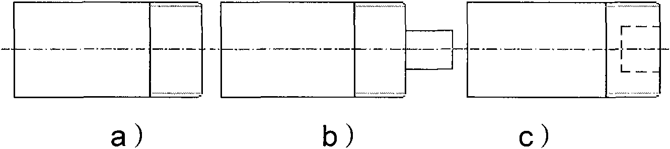
[0042] like Figure 5 Shown is the clamping schematic diagram of the second embodiment of the lathe positioning fixture of the present invention. This embodiment is used to process slender blind hole parts with high requirements on the coaxiality of the inner and outer circles. The outer surface has no external thread, as in this embodiment. The part 3 to be processed is an elongated shell part. like Figure 5 In the shown embodiment, the positioning body 1 is an axial positioning body, which provides an axial positioning reference for the parts after drilling and boring; 1 The external surface thread is matched with the internal thread.

[0043] The specific clamping and positioning process of the positioning fixture in this embodiment is as follows:

[0044] Step 1. Clamp the part 3 to be processed on the machine tool first, turn out the end face, blind hole and process external thread with a larger diameter than the designed outer circle, and cut off after leaving a marg...

Embodiment 3

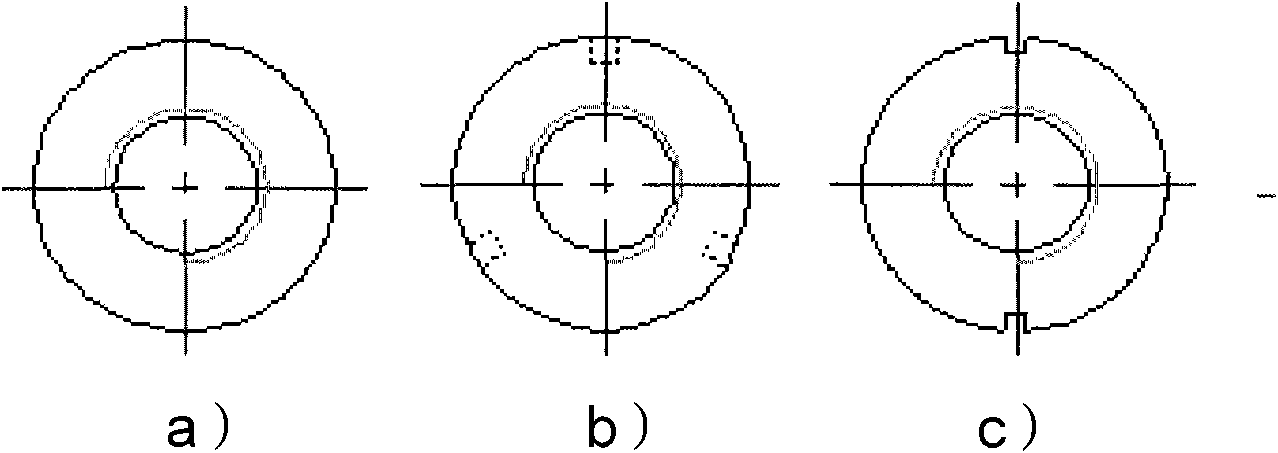
[0049] like Figure 6 Shown is the clamping schematic diagram of the third embodiment of the lathe positioning furniture of the present invention, this embodiment is used for processing parts with high parallelism and perpendicularity requirements with external threads, such as the part 3 to be processed in this embodiment is Sensor base. like Figure 6 In the present embodiment shown, the positioning body 1 is an end face positioning body, and the central drilling 6 is used to accommodate the thin shaft of the part to be processed, and the end face of the positioning body 1 is in contact with the step of the part to be processed 3 to provide an end face positioning reference; the threaded ring 4 The outer surface is knurled, and the inner surface is machined with internal threads matching the outer surface threads of the part 3 to be processed and the positioning body 1; the part 3 to be processed is a multi-step base with a slender shaft, and the parallelism of each step su...


PUM


Abstract

The invention relates to a turning positioning fixture for thin-wall rotational parts and a clamping method. The fixture comprises a cylindrical positioning body and threaded rings, wherein an external thread is lathed on the external surface of the positioning end; the threaded rings are circular rings with internal diameter the same as the external diameter of the positioning body; the internal surfaces of the threaded rings are provided with internal threads matched with the external thread on the positioning body; and during positioning, one end of the positioning body is clamped on a machine tool and the positioning end is closely contacted with the part, and the positioning body is closely matched with the part through the external thread on the external surface and the internal threads on the threaded rings. In the embodiment, the clamp force on the part is mainly axial force, thus overcoming the negative effect that radial force leads to workpiece deformation during traditional machining; and the positioning body is clamped and lathed at the site, and during positioning and clamping, firstly the positioning body is ensured to be fit with the end face of the part and the end face runout of the part is ensured to be identical with that of the spindle of the machine tool, thus ensuring the flatness and the parallelism of the part. The fixture can carry out automatic alignment and positioning while screwing the threaded rings, is convenient to operate and reduces artificial operation errors.

Description

technical field [0001] The invention relates to a positioning and clamping tool for turning machining, in particular to a lathe positioning fixture and a clamping method for thin-walled revolving body parts. Background technique [0002] When processing rotary parts with thin walls, high parallelism and flatness requirements on ordinary machine tools, there are processing defects due to machine tool precision and traditional clamping methods, such as low machine tool precision, multiple clamping during processing, axial The positioning center is not easy to find, direct clamping is easy to cause the thin-walled parts to be deformed by radial force, etc., which makes the processing of parts difficult, the scrap rate is high, and it is difficult to obtain the accuracy required by the design drawings, which not only reduces work efficiency, but also increases Cost of production. Especially for delicate products, it will cause huge losses. Contents of the invention [0003] ...

Claims


Application Information

Patent Timeline
Patent Type & Authority Applications(China)
IPC IPC(8): B23Q3/12
Inventor 赵谦益王燕生田军霞
Owner BEIJING RES INST OF TELEMETRY
Why Eureka
Try Eureka