
Trimming head for polishing pad

A polishing pad and rotary joint technology, which is applied in the direction of grinding/polishing equipment, abrasive surface adjustment devices, grinding machine parts, etc., can solve the problems of insufficient compactness and complex structure, and achieve high practicability, stable and reliable movement, Compact and beautiful effect

Active Publication Date: 2011-02-16
HWATSING TECH
View PDF5 Cites 10 Cited by
  • Summary
  • Abstract
  • Description
  • Claims
  • Application Information

AI Technical Summary

Problems solved by technology

[0004] In order to overcome the shortcomings of the existing polishing pad dressing head with complex structure and not compact enough, the present invention provides a polishing pad dressing head with simple and compact structure, which is easy to process and assemble

Method used


Image

  • Trimming head for polishing pad
  • Trimming head for polishing pad

Examples


Embodiment Construction

[0017] The present invention provides a polishing pad dressing head, and the present invention will be further described below in conjunction with the accompanying drawings and specific embodiments:

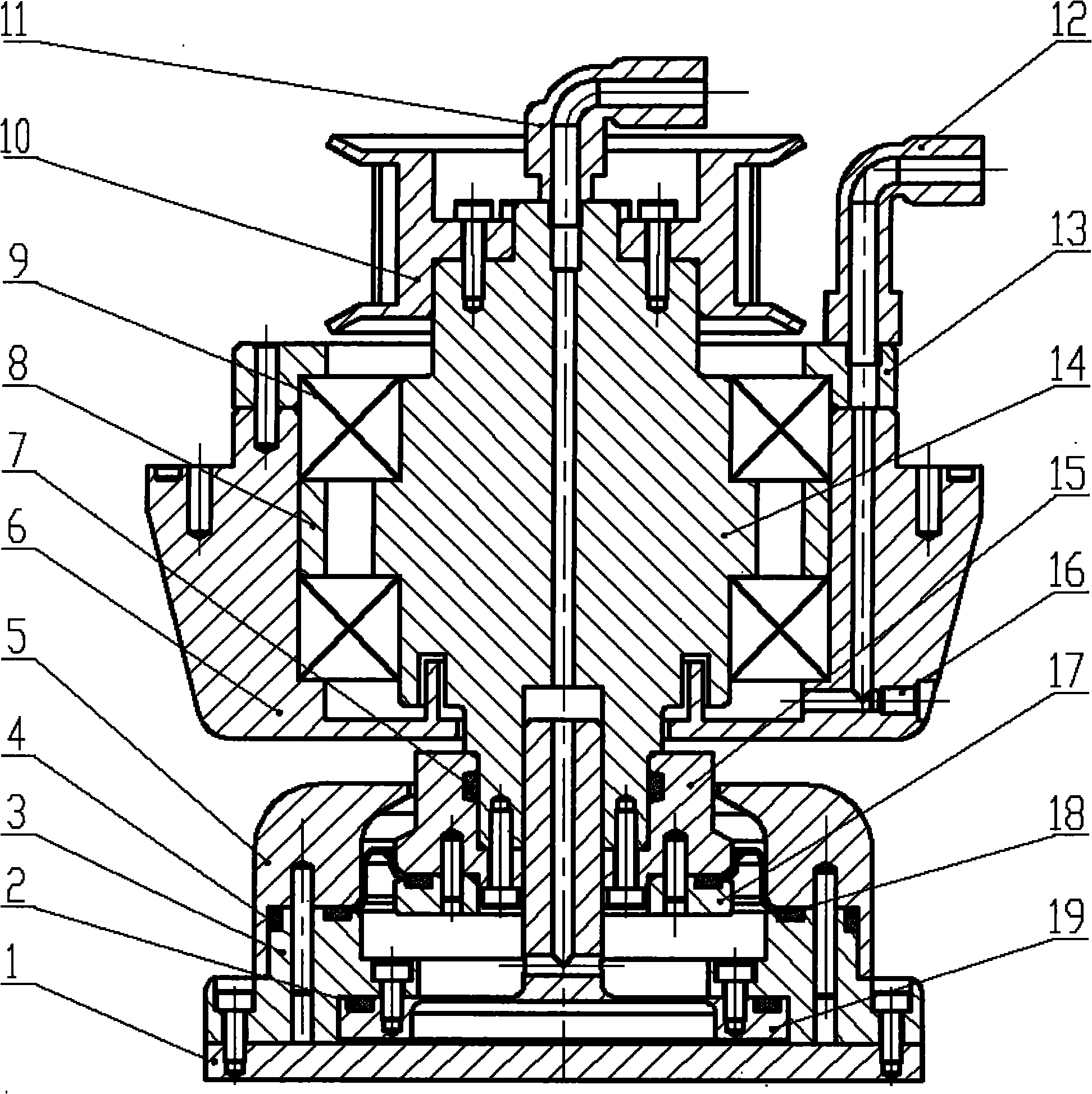
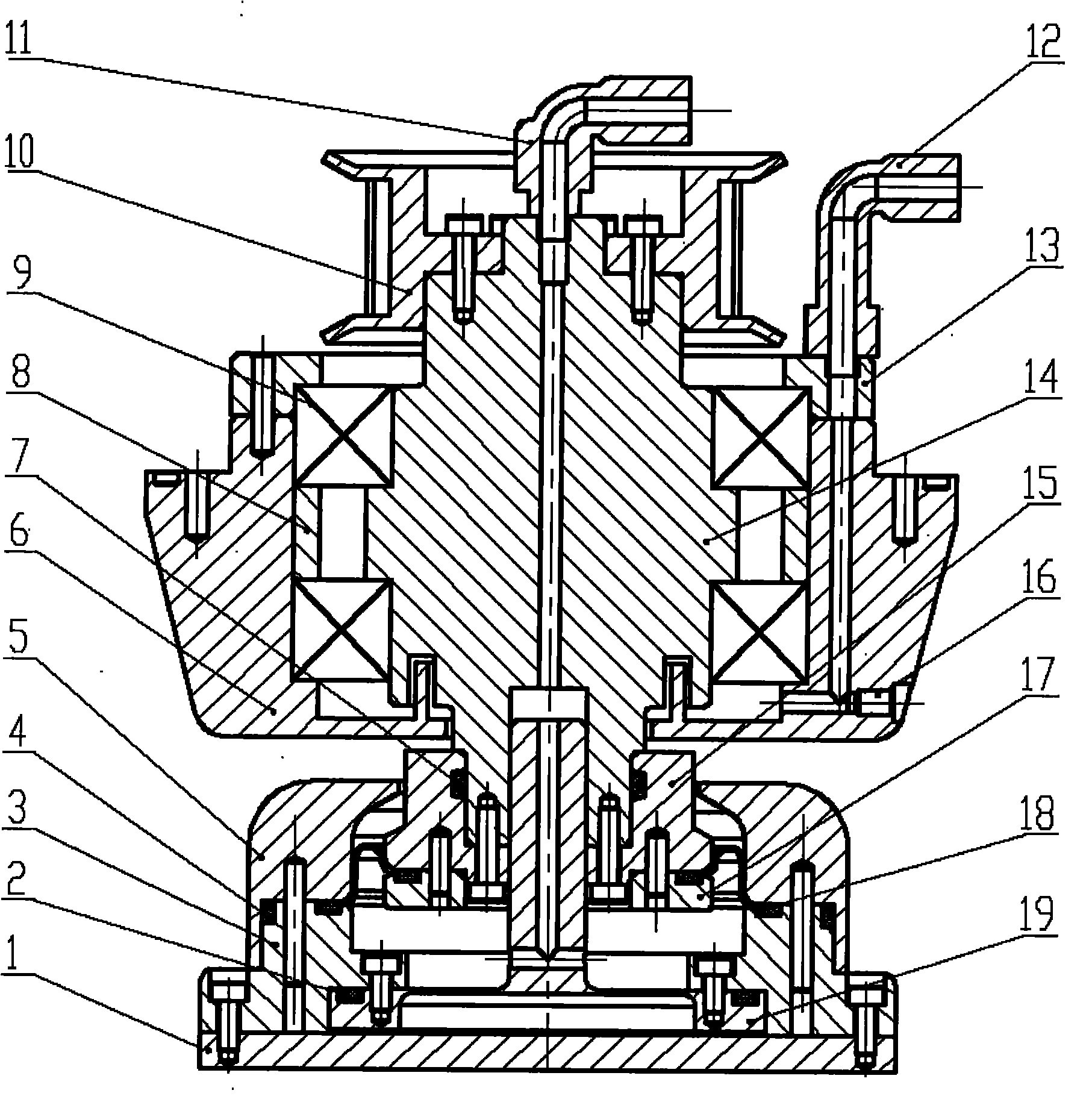
[0018] like figure 1 As shown, the main shaft 14 is axially positioned by two sets of bearings 9 to avoid the axial movement of the main shaft. The bearings 9 are installed and fixed in the bearing housing 6 through the bearing end cover 13 and the sleeve 8; the bearing housing 6 and the bearing end cover 13 are arranged There are connected air holes, and the quick-change joint 12 is installed on the air hole of the bearing end cover 13; the seal between the main shaft 14 and the bearing seat 6 includes a labyrinth seal and an air seal; the top of the main shaft 14 is fixedly connected with the timing belt 10 by screws, The bottom end of the main shaft 14 is fixedly connected with the flange 15 and the pressure plate 17 by screws; the protective cover 5, the pressure plate 3, the...


PUM


Abstract

The invention relates to the technical field of chemical machinery polishing equipment, in particular to a trimming head for a polishing pad. A main shaft is positioned axially through two groups of bearings so as to avoid axial vibration of the main shaft; the bearings are arranged and fixed in a bearing block through a bearing end cap and a sleeve; a communicated air hole is formed on each of the bearing block and the bearing end cap, and a quick-change connector is arranged on the air hole of the bearing end cap; a seal between the main shaft and the bearing block comprises a labyrinth seal and an air seal; the top of the main shaft is fixedly connected with a synchronous belt through a screw, and the bottom of the main shaft is fixedly connected with a flange and a tabletting through the screw; a protective cover, a pressure plate, an adaptive plate and a diamond plate are integrated into a whole through the screw, and the flange and the tabletting are covered and fixed; and the flange and the tabletting as well as the flange and the protective cover are connected with through a compression flexible ring. The trimming head for the polishing pad has a simple and compact structure and attractive appearance, is easy to machine and assemble, stable and reliable in movement and very practical and can be widely used for the polishing equipment.

Description

technical field [0001] The invention relates to the technical field of chemical mechanical polishing equipment, in particular to a polishing pad dressing head. Background technique [0002] In chemical mechanical polishing equipment, after the polishing pad is used for a period of time, with its own wear and the filling of micropores on the surface of the polishing pad by abrasive debris, the surface of the polishing pad becomes smooth, forming a glazed layer, so that the polishing pad stores and transports abrasives Reduced capacity, resulting in reduced material removal rate and polished surface quality. Proper dressing of the polishing pad by the diamond disk on the dressing head can remove the glaze layer and abrasive debris on the polishing pad, improve the roughness and service life of the polishing pad, reduce costs, and ensure polishing consistency. The dressing head drives the diamond disc to press down to contact the polishing pad, and drives the diamond disc to r...

Claims


Application Information

Patent Timeline
Patent Type & Authority Applications(China)
IPC IPC(8): B24B53/12
CPCB24B53/017
Inventor 路新春沈攀何永勇雒建斌
Owner HWATSING TECH
Learn More