Lip and spread angle variable efficient duct

A diffusion angle, variable technology, applied in the lip and diffusion angle variable high-efficiency duct, the duct that generates thrust on the aircraft, and the duct field, which can solve the response delay, difficult to achieve, and reduce the size of the lip. Negative pressure value and other problems to achieve the effect of improving efficiency, improving accuracy and reducing coupling effect

Inactive Publication Date: 2011-02-16
BEIJING INSTITUTE OF TECHNOLOGYGY
View PDF4 Cites 18 Cited by
  • Summary
  • Abstract
  • Description
  • Claims
  • Application Information

AI Technical Summary

Problems solved by technology

[0003] At present, when the ducted propeller and ducted fan (hereinafter referred to as ducted propeller) used to generate thrust or lift are used to control the force output, it is generally used to change the speed of the propeller or the propeller pitch (blade angle of attack). Changing the magnitude of the force, this adjustment process is accompanied by the change of the rotating state of the high-speed rotating propeller, which needs to overcome the huge change of moment of inertia or change of aerodynamic force, so the response of the adjustment process has a certain degree of delay. For aircraft with attitude control, it has some adverse effects
In addition, since the torque generated by the ducted propeller needs to be balanced and offset so that the aircraft does not spin, the traditional tension control system will cause changes in the spin torque during the process of changing the tension, so the control has a coupling effect, which will be due to Changes in the control of the pulling force cause changes in other quantities, increasing the difficulty of control
In foreign countries, there is also a method of compensating the pressure by opening air holes at the lip, reducing the negative pressure at the lip, thereby changing the additional pulling force of the lip, but this method can only weaken and adjust the original pulling force, and cannot achieve a wider range. Increase or decrease adjustment
At present, there is also a plan to change the pressure distribution of the flow field in the duct through a plasma generator in the world, but because the technology is complex, it is not easy to realize, and there are certain difficulties. It is currently in the laboratory research stage.

Method used


Image

  • Lip and spread angle variable efficient duct
  • Lip and spread angle variable efficient duct
  • Lip and spread angle variable efficient duct

Examples


Embodiment Construction

[0017] The preferred embodiments of the present invention will be further described below in conjunction with the accompanying drawings.

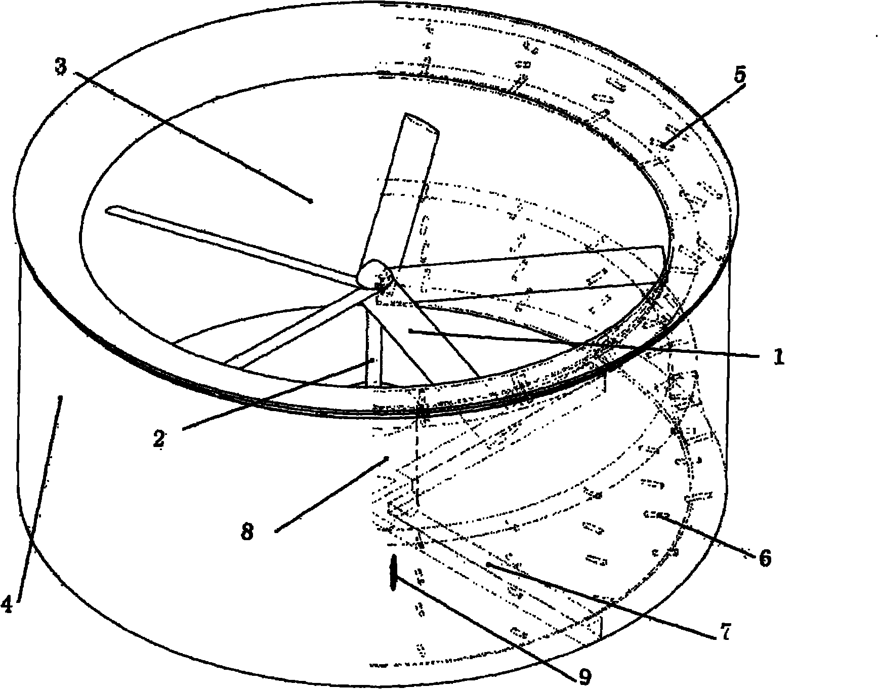
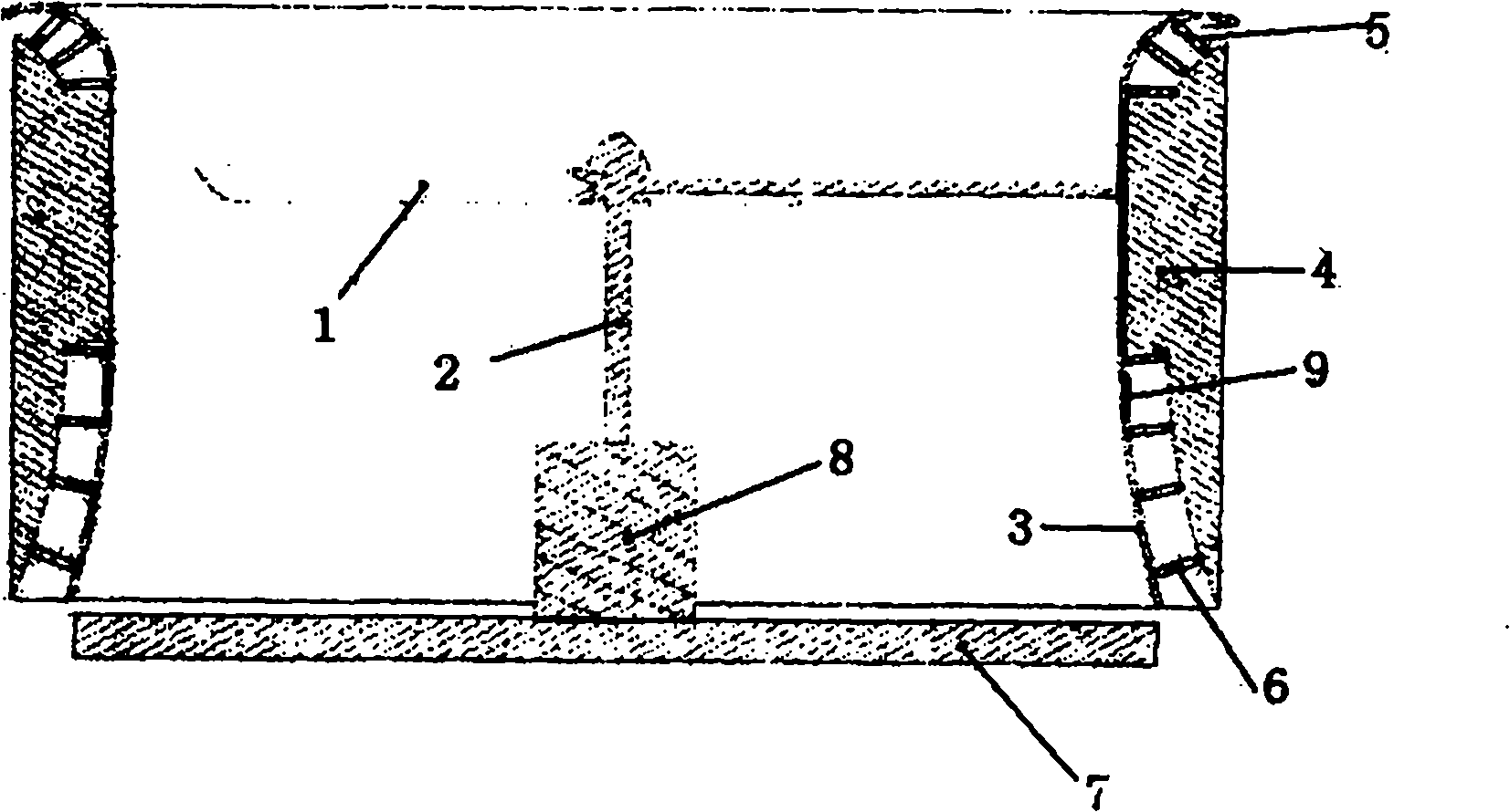
[0018] Figure 1 to Figure 3 Shown is a high-efficiency duct with a variable lip and divergence angle realized according to the present invention. The material used for the duct wall 3 is a flexible material with a certain strength. The upper and lower ends of the duct wall 3 are respectively fixed with multiple lip actuators 5 and diffuser actuators 6. The actuators 5 and 6 are separately fixed. One end is connected on the positioning platform 4. The flexible material may be rubber or other materials with certain elasticity that can form a thin-walled structure. The actuators 5 and 6 can use hydraulic cylinders, or stepper motors and lead screws to perform linear reciprocating motions under control signals to change the distance between the two ends of the actuators 5 and 6 . One end of the actuators 5 and 6 is hinged to the duct flexib...


PUM


Abstract

The invention relates to a lip and spread angle variable efficient duct which is made of flexile duct wall materials. The upper end and the lower end of the outer side of the duct are fixed with at least one actuating cylinder, and the other end of the actuating cylinder is connected to a positioning rack. A numerical value sensor is arranged on the side wall above a spread opening of the duct and used for sensing whether air flow is separated or not due to the increased spread angle of the opening and feeding a sensor signal back to an ECU (Electronic Control Unit). Part or all regions of the inner wall of the duct are provided with pit features which can be adjustable pit flexible pasters consisting of MEMSs (Micro Electro Mechanical Systems). The duct can be used for regulating the lip and the tail spread angle in real time, can improve the efficiency of duct propellers, and can change the duct pull force under the condition of no change of other control conditions, improve the control accuracy, and reduce the coupling function in the aircraft control.

Description

technical field [0001] The invention relates to a duct, in particular to a high-efficiency duct with a variable lip and divergence angle, which belongs to the technical field of propeller (duct fan) aerodynamics, and is especially suitable for ducts that generate thrust on aircraft. Background technique [0002] With the development of vertical take-off and landing aircraft, ducted propellers and ducted fans have flourished in recent years and are widely used in many unmanned aerial vehicles and special aircraft. [0003] At present, when the ducted propeller and ducted fan (hereinafter referred to as ducted propeller) used to generate thrust or lift are used to control the force output, it is generally used to change the speed of the propeller or the propeller pitch (blade angle of attack). Changing the magnitude of the force, this adjustment process is accompanied by the change of the rotating state of the high-speed rotating propeller, which needs to overcome the huge cha...

Claims


Application Information

Patent Timeline
Patent Type & Authority Applications(China)
IPC IPC(8): A63H27/24B64C11/00
Inventor 项昌乐徐彬袁海涛李明喜
Owner BEIJING INSTITUTE OF TECHNOLOGYGY
Why Eureka
Try Eureka