
Damping device

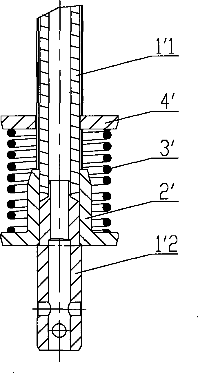
A buffer device and set technology, applied in drilling equipment, earthwork drilling, drill pipe, etc., can solve the problems of fracture, reduce work efficiency, spring 3' fatigue damage, etc., to reduce the probability of damage, reduce labor intensity, Overall strength enhancement effect

Inactive Publication Date: 2011-02-16
BEIJING SANY HEAVY MASCH CO LTD
View PDF5 Cites 5 Cited by
  • Summary
  • Abstract
  • Description
  • Claims
  • Application Information

AI Technical Summary

Problems solved by technology

[0005] However, when the buffer device in the above-mentioned prior art is under load, the drill rod will press the spring 3' as a whole due to its own overweight, that is, due to excessive labor intensity, the compressed amount of the spring 3' exceeds the spring compression design value, causing the spring 3' to be compressed. 3′ premature fatigue damage and fracture
When the spring 3' is damaged or broken, it is necessary to immediately shut down and repair or replace the spring 3', thus significantly reducing the work efficiency

Method used


Image

  • Damping device
  • Damping device
  • Damping device

Examples


Embodiment Construction

[0031] The core of the present invention is to provide a buffer device, which can significantly reduce the labor intensity of the main spring, reduce its damage probability, and thus prolong its service life.

[0032] In order to enable those skilled in the art to better understand the technical solutions of the present invention, the present invention will be further described in detail below in conjunction with the accompanying drawings and specific embodiments.

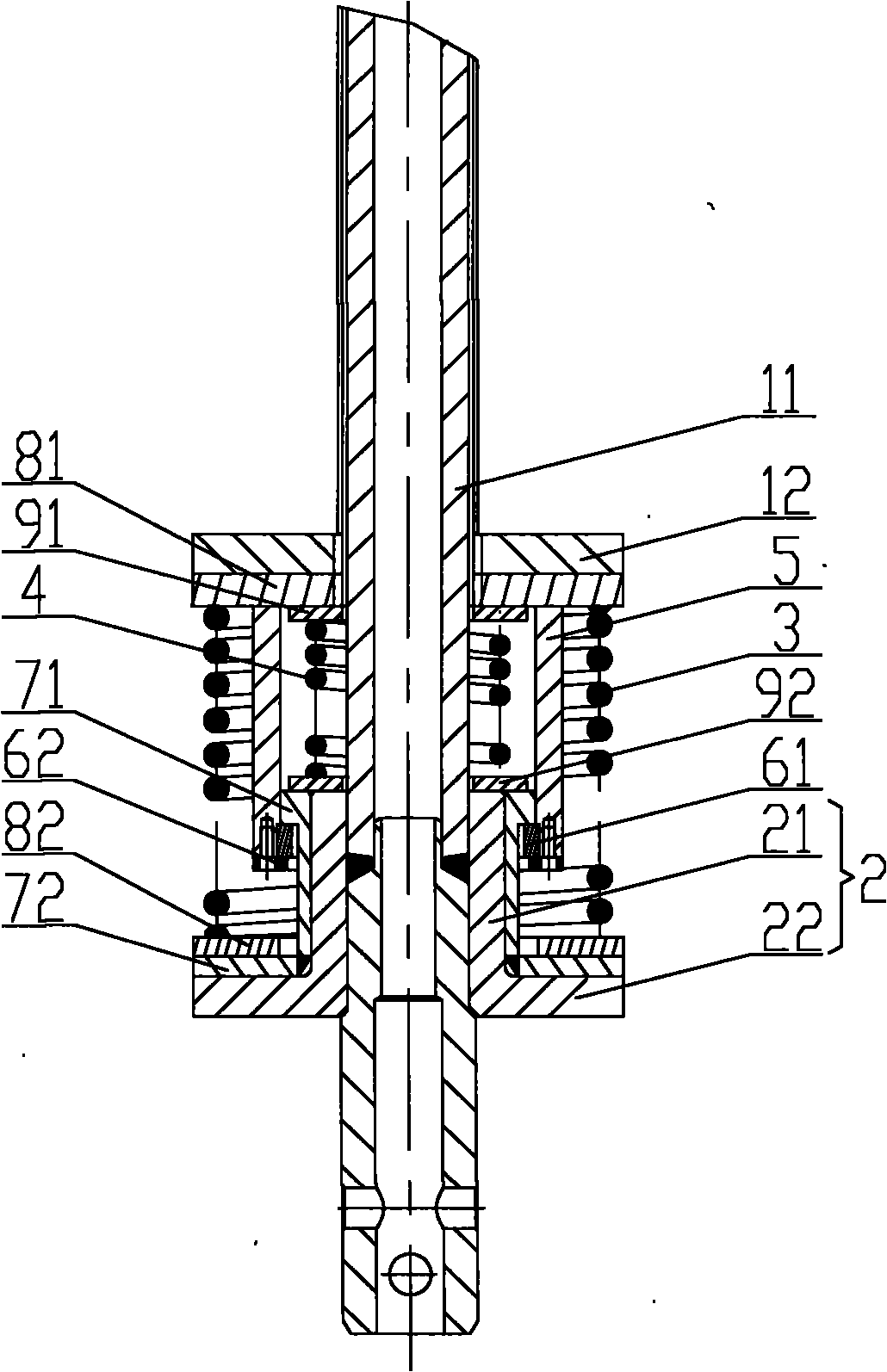
[0033] Please refer to image 3 and Figure 4 , image 3 It is a structural schematic diagram of the buffer device in a free state in an embodiment of the present invention; Figure 4 for image 3 Schematic diagram of the structure of the buffer device in a compressed state.

[0034] In one embodiment, the buffer device provided by the present invention includes a spring seat 2, a main spring 3 and a tray 12, the spring seat 2 is set on the outside of the drill rod 11, the tray 12 is set on the outside of the d...


PUM


Abstract

The invention discloses a damping device, which is used for a rotary drilling rig. The damping device comprises a spring seat (2) which is sleeved outside a drill stem (11) of the rotary drilling rig, wherein a main spring (3) is supported on the spring seat (2); a pallet (12) which is sleeved outside the drill stem (11) is supported above the main spring (3); and an auxiliary spring (4) is further arranged between the spring seat (2) and the pallet (12). The damping device has the advantages of obviously reducing the work intensity of the main spring (3) and reducing the damage probability of the main spring (3) so as to prolong the service life of the main spring (3).

Description

technical field [0001] The invention relates to the technical field of rotary drilling rigs, in particular to a buffer device. Background technique [0002] At present, during the construction of the rotary drilling rig, the phenomenon of overhead or rods often occurs between the steel pipes of each layer of the drill pipe. When the drill pipe is pressurized, the drill pipe will suddenly produce a vertical downward impact on the pallet, and at the same time Impact force will be generated on the wire rope connecting the flat head and winch, causing damage to the drill pipe tray, locking and tripping of the wire rope or breaking of the wire rope, so a buffer device is added under the tray. [0003] Please refer to figure 1 and figure 2 , figure 1 It is a structural schematic diagram of a typical buffer device in the prior art; figure 2 for figure 1 Top view of the buffer device. [0004] The rotary drilling rig includes a drill rod, and the drill rod includes a core ro...

Claims


Application Information

Patent Timeline
IPC IPC(8): E21B17/07
Inventor 赵锡鹏金亚凤
Owner BEIJING SANY HEAVY MASCH CO LTD
Learn More