
Flexible non-collision cold-finger limiting protecting device

A protective device and flexible technology, applied in the field of flexible non-collision cold finger limit protection device, can solve the problems of cold finger damage, single-point contact, local impact force, etc., and achieve the effect of protecting cold finger and convenient operation

Active Publication Date: 2011-02-16
SHANGHAI INST OF TECHNICAL PHYSICS - CHINESE ACAD OF SCI
View PDF5 Cites 0 Cited by
  • Summary
  • Abstract
  • Description
  • Claims
  • Application Information

AI Technical Summary

Problems solved by technology

However, the main problem of this limiting method is that the shape of the cold finger and the limiting sleeve is generally cylindrical, and the contact between them is a single-point contact.
When the vibration is severe, the local impact force caused by the collision on the head of the cold finger may be very large, causing damage to the cold finger; the limit is realized by collision, and only at a certain moment, the cold finger may be affected by the collision. The impact of the instantaneous stress impulse may cause a large impact load on the cold finger

Method used


Image

  • Flexible non-collision cold-finger limiting protecting device
  • Flexible non-collision cold-finger limiting protecting device
  • Flexible non-collision cold-finger limiting protecting device

Examples


Embodiment Construction

[0020] The present invention is described in detail in conjunction with accompanying drawing now.

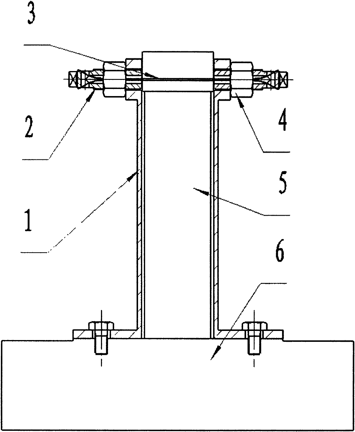
[0021] figure 1 As shown, the flexible non-collision cold finger protection device of the present invention comprises an outer support 1 , a locking bolt 2 , a Kevlar fiber 3 and a pre-tightening nut 4 .

[0022] First fix the cold finger 5 of the refrigerator on the test base plate or the frame 6 in advance, and then install the protection device.

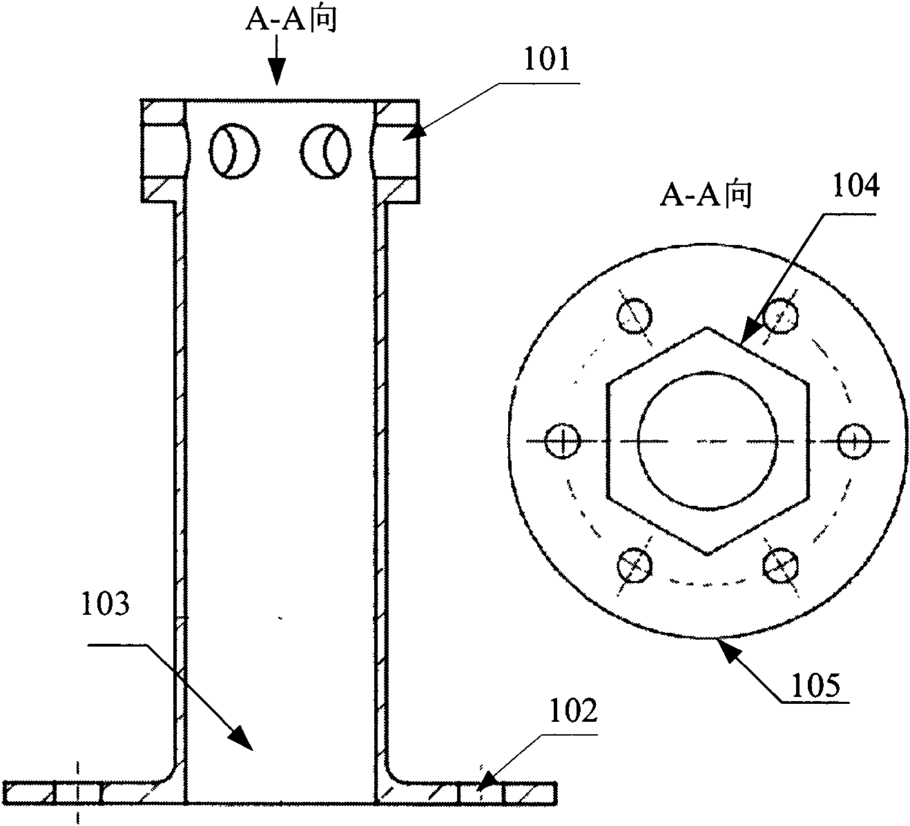
[0023] figure 2 As shown, the outer support 1 is made of stainless steel, which is a revolving body, and the section along the axis is "I"-shaped, and its height is slightly lower than the length of the cold finger; there is a through hole 1-03 in the central axis, which can be larger than the outer diameter of the cold finger 5 The size is 4-6mm; the top flange 1-04 is a regular hexagon, and the center of each side wall of the flange is opened with a through hole 1-01 in the radial direction, and the outer diameter is slightly l...


PUM


Abstract

The invention discloses a flexible non-collision cold-finger limiting protecting device which comprises an I-shaped outer support, six fiber joints, six pretightening nuts and three Kevlar fibers and is mainly characterized in that a flange at the top end of the outer support is orthohexagonal, and a through hole is respectively drilled at the centers of side walls of the outer support. A round flange is arranged at the bottom of the outer support, and six fixed holes are arranged on the circumference of the outer support. Each fiber is oppositely folded into double strands, and both ends are connected through the fiber joints to form a closed curve. Thus, when the three groups of fiber joints are respectively and symmetrically installed in the through holes on the lateral walls of the symmetrical surfaces of the flange at the top end of the outer support, six fiber nets which are staggered and radially arranged are formed at the center of the outer support, and the head of a cold finger is hooped in an enveloping area surrounded by the centers of the fibers. The pretightening nuts are in external threaded fit with the fiber joints, support against the lateral walls of the flange from the outer side and are used for providing the initial pretightening force of the fibers to bind the cold finger. The whole device is fastened on a testing soleplate or a base through the flange at the bottom of the outer support. The invention has the largest advantages that the transient stress impulse generated by collision to the cold finger can not appear in vibration testing, and the damage caused by position limitation to the cold finger is markedly decreased; and the contact area of the fibers and the cold finger is large, and the local stress of a limiting point is reduced.

Description

technical field [0001] The invention relates to a cold finger limit protection device in a space mechanical refrigerator, in particular to a flexible non-collision cold finger limit protection device. Background technique [0002] The coupling system of the infrared detector and the space mechanical refrigerator is one of the key components in the infrared remote sensing system. In addition to providing the interface between the infrared detector and the mechanical refrigerator and cooling the infrared detector to the working temperature by heat exchange, it also has The support and positioning of the detector provide the function of the electrical connection channel between the infrared imaging signal processing system and the detector. Usually, a flexible cold chain or a mixture of flexible cold chain and heat conducting rod is used to connect the detector and the cold finger of the refrigerator. This heat transfer structure connecting the cold finger and the detector wil...

Claims


Application Information

Patent Timeline
Patent Type & Authority Applications(China)
IPC IPC(8): G01M7/02
Inventor 李奥张利刘冬毓吴亦农
Owner SHANGHAI INST OF TECHNICAL PHYSICS - CHINESE ACAD OF SCI
Learn More