Laser ranging device

A laser ranging and optical path technology, applied in measuring devices, radio wave measurement systems, electromagnetic wave re-radiation and other directions, can solve the problems of inability to rotate the rotor, large starting torque, deflection of the rotor shaft, etc., to avoid jitter or deflection , The effect of reducing the starting torque and reducing the driving power consumption

Inactive Publication Date: 2011-02-16
江苏精湛光电仪器股份有限公司
View PDF4 Cites 2 Cited by
  • Summary
  • Abstract
  • Description
  • Claims
  • Application Information

AI Technical Summary

Problems solved by technology

[0005] 1. The reflector is installed on the rotor shaft of the micro motor. Because the part of the rotor shaft protruding from the motor is a cantilever structure, the weight of the reflector relative to the rotor shaft is relatively heavy, which will cause the rotor shaft to deflect and affect the position of the reflector. Accuracy; In addition, the vibration of the motor rotor shaft itself will also affect the accuracy of the position of the reflector
[0006] 2. The reflector is installed on the rotor shaft of the micro motor and one end is pulled on the fixed pin by a tension spring. The self-weight of the reflector itself requires a large starting torque of the motor; when the motor drives the reflector to rotate, it must first overcome the force of the tension spring tension, making it difficult to start the motor initially
[0008] 4. The inner optical path assembly is not an independent structure, and the rotation stroke of the reflector needs other devices to limit the position, otherwise it will rotate freely and the angle is too large
[0009] 5. The micro-motor is fixed on the inner light path assembly through a clamp. Since the power of the micro-motor is very small, the gap between the rotor and the stator is very small. If the clamp is too tight, the motor will be partially deformed and the rotor cannot rotate; if it is too loose, will misalign the position of the reflector
Even if the clamp is adjusted to the appropriate tightness during debugging, it will still be stuck or loosened as the temperature changes in the seasons

Method used


Image

  • Laser ranging device
  • Laser ranging device
  • Laser ranging device

Examples


Embodiment Construction

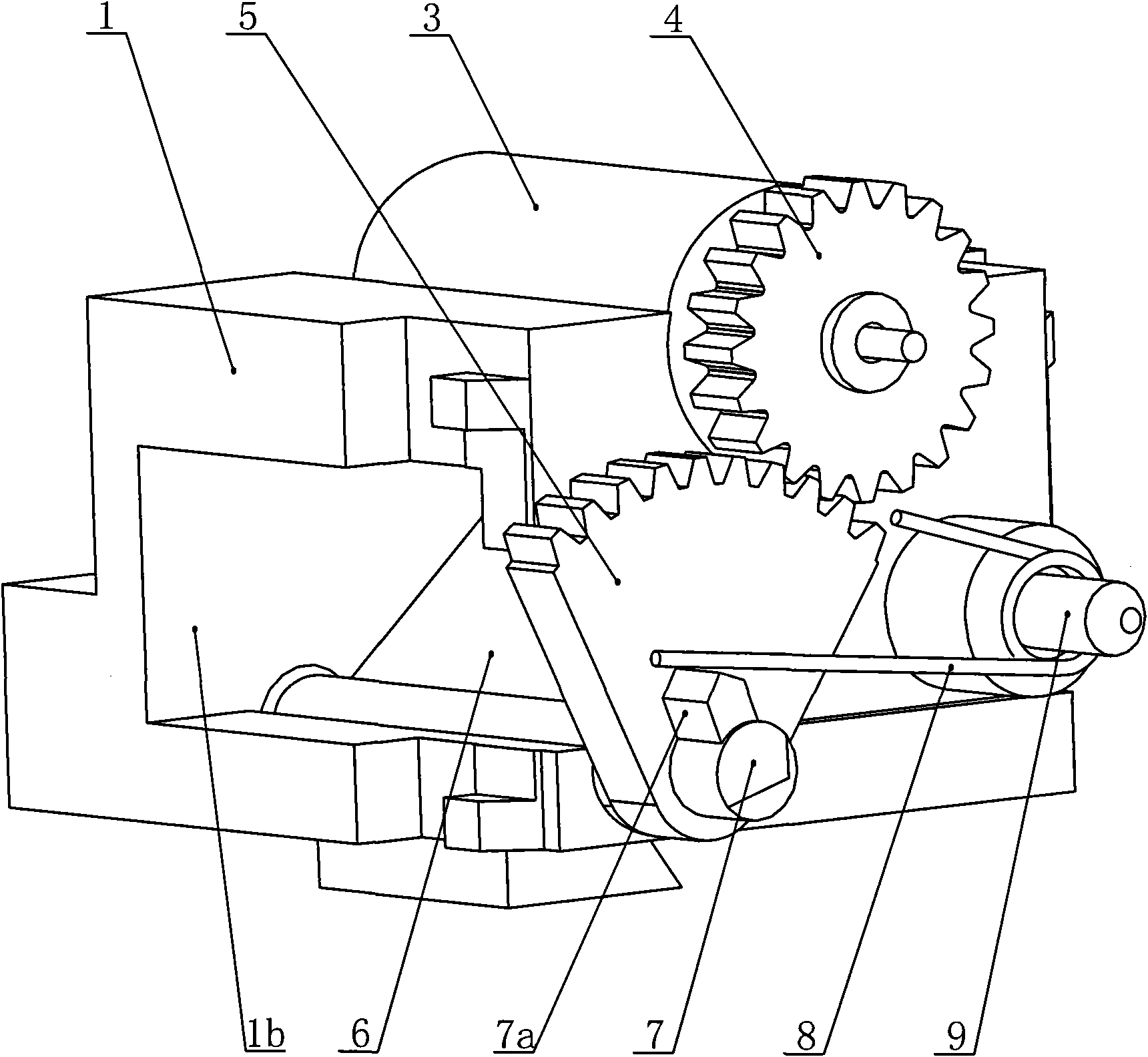
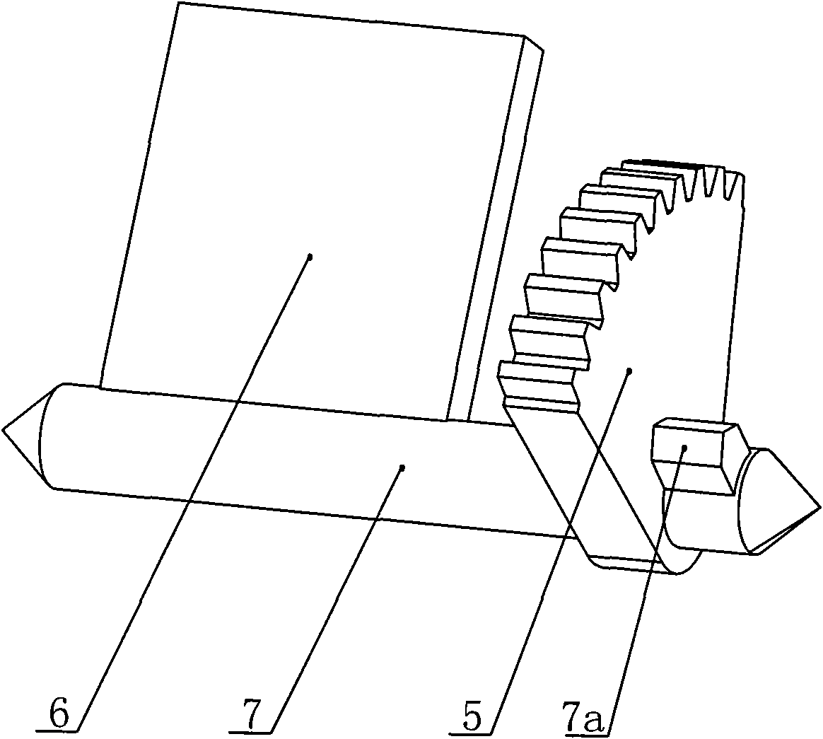
[0032] Such as figure 2 and image 3 As shown, the inner optical path assembly of the laser distance measuring device of the present invention includes an inner optical path assembly seat 1 , a micro motor 3 , a cylindrical gear 4 , a sector gear 5 and a movable reflector 6 . The movable reflector 6 is located in the cavity of the inner optical path assembly seat 1, and its root is provided with a reflector shaft 7 and can rotate around a certain angle around the reflector shaft 7. The shaft end of the reflector shaft 7 is equipped with a sector gear 5, a sector gear 5 Mesh with the cylindrical gear 4, the cylindrical gear 4 is installed on the output shaft of the micro motor 3, and the micro motor 3 is installed in the motor installation groove 1a of the inner optical path assembly seat 1.

[0033] Such as Figure 4 As shown, the motor mounting groove 1a is located on the upper part of the inner optical path assembly seat 1, and its cross section is a semicircle slightly g...


PUM


Abstract

The invention discloses a laser ranging device, comprising a machine body and an inner optical system assembly, wherein the inner optical system assembly comprises an inner optical system assembly base, a micro motor, a cylindrical gear, a sector gear, a movable reflector and a torsion spring for locking the reflector; the movable reflector is positioned in the cavity of the inner optical system assembly base and is provided with a reflector rotating shaft at the root; the end of the reflector rotating shaft is provided with the sector gear; the sector gear is meshed with the cylindrical gear with clearance; the cylindrical gear is installed on the micro motor shaft; the micro motor is installed in a motor installation groove of the inner optical system assembly base; the cross section of the motor installation groove is slightly bigger than the 180-degree semicircle; the front end of the reflector rotating shaft is provided with a reflector locking convex body; the front end face of the inner optical system assembly base is provided with a torsion spring installation column and a torsion spring tension pin which are parallel with the reflector rotating shaft; the torsion spring is sleeved on the torsion spring installation column; and two spring plates of the torsion spring are respectively pressed on the torsion spring tension pin and the reflector locking convex body. The laser ranging device has simple structure and accurate test results and is reliable in operation.

Description

technical field [0001] The invention relates to a distance measuring device, in particular to a laser distance measuring device, which measures the distance through a laser beam. Background technique [0002] The laser distance measuring device is an instrument that uses laser to accurately measure the distance of the target. The laser range finder emits a very thin laser beam to the target when it is working, and the photosensitive element receives the laser beam reflected by the target. The timer measures the time from the launch to the reception of the laser beam, and calculates the distance from the observer to the target. [0003] Such as figure 1 As shown, the time from the laser controller to the laser is t1, the time from the laser to the target and back to the photosensitive element is t2, and the time from the photosensitive element to the signal receiver is t3. In the measurement, the time t2 from the laser to the target and back to the photosensitive element is...

Claims


Application Information

Patent Timeline
Patent Type & Authority Applications(China)
IPC IPC(8): G01S7/481G01S17/08
Inventor 赵玉忠
Owner 江苏精湛光电仪器股份有限公司
Why Eureka
Try Eureka