Relaxation-type voltage-controlled oscillator

A technology of voltage-controlled oscillators and logic control circuits, applied in automatic power control, electrical components, etc., can solve problems such as complete matching of current sources, inability to generate differential output, low operating frequency, etc., and achieve high process consistency , simple structure and short oscillation period

Inactive Publication Date: 2011-02-16
苏州工业园区银盛智能科技有限公司
View PDF4 Cites 11 Cited by
  • Summary
  • Abstract
  • Description
  • Claims
  • Application Information

AI Technical Summary

Problems solved by technology

can be controlled by the capacitor C T Charge and discharge current I 1 , I 2 To control the oscillation period, but this kind of oscillator needs to generate an accurate reference voltage value externally to complete the comparison oscillation, and cannot generate differential output, and at high frequencies, due to the delay of the gate, the

Method used


Image

  • Relaxation-type voltage-controlled oscillator
  • Relaxation-type voltage-controlled oscillator
  • Relaxation-type voltage-controlled oscillator

Examples


Embodiment 1

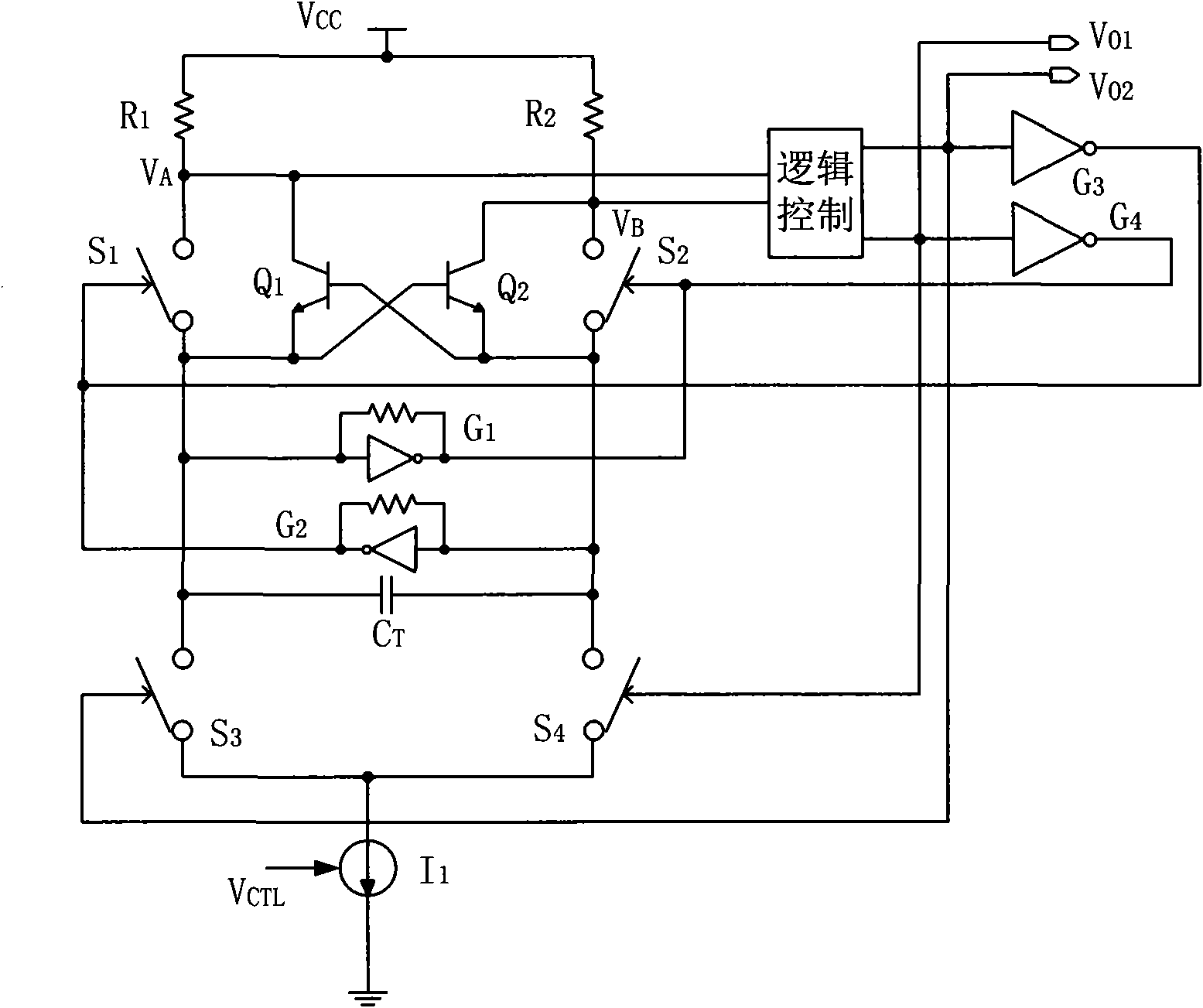
[0024] Embodiment one: see image 3 As shown, a relaxation-type voltage-controlled oscillator includes a charging capacitor, a switch tube assembly, a comparator circuit, a charging current source and a logic control circuit connected to form: one said charging current source is included; the switch tube assembly is composed of the first 1. The second group of 4 switching tubes S 1 ~S 4 Composition, the first group of switching tubes is S 1 , S 4 , the second set of switching tubes is S 2 , S 3 , where the switch tube S 1 , S 2 The control end of the logic control circuit is connected to the output end of the logic control circuit, and the switch tube S 3 , S 4 The control terminal and the oscillator output V O1 , V O2 connection, the two switching tubes in each group are connected in series, the contacts at one end of the first and second group of switching tubes are respectively connected to the charging current source, and the contacts at the other end are respect...

Embodiment 2

[0030] Embodiment two: see Figure 4 As shown, the present invention is used in the IF phase-locked loop demodulator of the TV receiver. In order to realize high-speed oscillation and have good linearity, all coupling tubes and switching tubes use bipolar transistors.

[0031] The core part is composed of 305, Q 6 , Q 7 , Q 10 , Q 11 are four switching tubes, Q 8 , Q 9 For the clamp tube, the control current source is provided by Q 12 ~Q 15 , R 10 ~R 12 composition; the control logic is composed of 309 and 311, 309 is a pair of inverters, 311 is a buffer, and has the function of level shifting; 303 is a pair of inverters; 305 is the realization image 3 G in 1 , G 2 circuit; resistance R 6 and R 7 is Q 10 and Q 11 The base bias resistors, changing their values ​​can adjust the static operating point, so that they are completely in the "on" or "off" state, and at the same time ensure that point A has an appropriate voltage value (this voltage value will directly ...


PUM


Abstract

The invention discloses a relaxation-type voltage-controlled oscillator, which is composed of a charging capacitor, a switching tube assembly, a comparison circuit, a charging current source and a logic control circuit, and is characterized by being provided with the charging current source which is formed by a constant current source and a controlled current source in parallel; the switching tube assembly is formed by a first group and a second group of four switches; the charging capacitor is connected with a first group of switching tubes and a second group of switching tubes; the comparison circuit is formed by a cross-coupled geminate transistor, and is connected with the two positive and negative ends of the charging capacitor; the cross-coupled geminate transistor comprises a first clamper tube and a second clamper tube, wherein, the input end of the first clamper tube is connected with the output end of the second clamper tube; and the input end of the second clamper tube is connected with the output end of the first clamper tube. The relaxation-type voltage-controlled oscillator of the invention adopts the break-over voltage of a semiconductor tube as a comparison voltage, improves the oscillating frequency through improving the structure of the controlled circuit source, has high linearity, adopts a current source to avoid the consistency problem of the process, and is easier to realize.

Description

technical field [0001] The invention relates to an oscillator, in particular to a relaxation type voltage-controlled oscillator used in a phase-locked loop (PLL). Background technique [0002] In modern communication systems, phase-locked loops (PLLs) have become ubiquitous due to their outstanding versatility (universal applicability, applicability). The so-called phase-locked loop is a feedback control circuit that uses an external input reference signal to control the frequency and phase of the internal oscillation signal of the loop. When the frequency of the output signal is equal to the frequency of the input signal, the output voltage and the input voltage remain fixed. The phase difference, that is, the phase of the output voltage and the input voltage is locked, mainly composed of a phase detector, a loop filter and a voltage-controlled oscillator, of which the voltage-controlled oscillator is the core component, and its function is to generate an oscillation freque...

Claims


Application Information

Patent Timeline
IPC IPC(8): H03L7/099
Inventor 李富华谢卫国赵鹤鸣王伟王汉祥杜坦
Owner 苏州工业园区银盛智能科技有限公司
Why Eureka
Try Eureka