Method and system for implementing automatic test of indexes of optical module

A technology for automated testing and optical modules, applied in the field of optical modules, to save test time and improve accuracy

Active Publication Date: 2011-02-16
浙江杭海新城控股集团有限公司
View PDF5 Cites 19 Cited by
  • Summary
  • Abstract
  • Description
  • Claims
  • Application Information

AI Technical Summary

Problems solved by technology

[0007] The technical problem to be solved by the present invention is to overcome the problems of optical power monitoring, sensitivity and overload point measurement by frequently manually adjusting the adjustable attenuator in the prior art, and proposes a Method and system for realizing automatic test of optical module index on single board

Method used


Image

  • Method and system for implementing automatic test of indexes of optical module
  • Method and system for implementing automatic test of indexes of optical module
  • Method and system for implementing automatic test of indexes of optical module

Examples


Embodiment Construction

[0046] In order to better understand the present invention, the present invention will be further described below in conjunction with the accompanying drawings and specific embodiments.

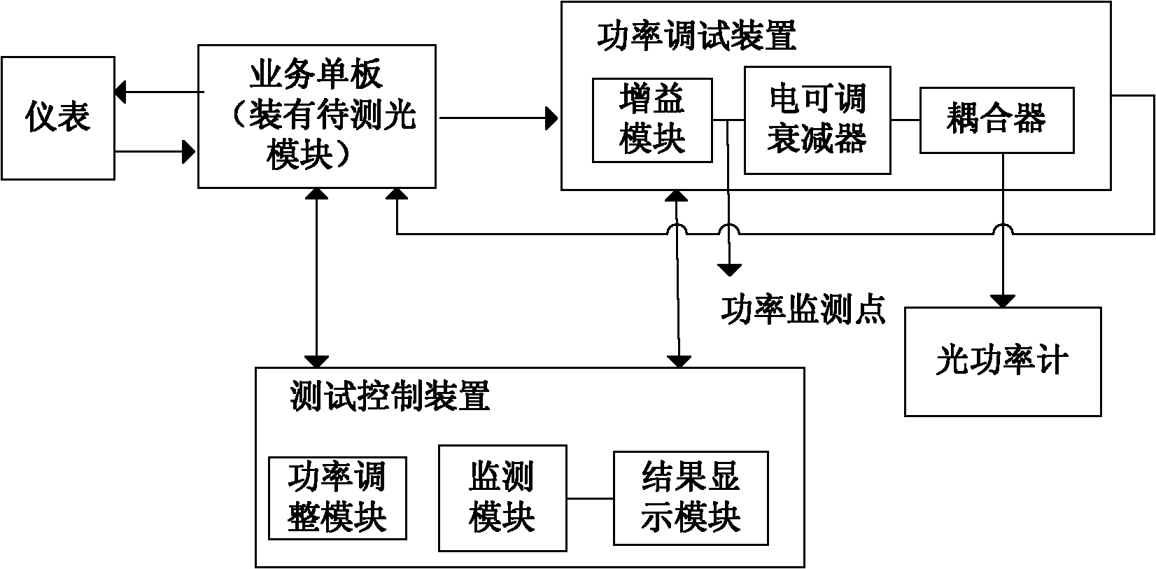
[0047] figure 1 It is a schematic diagram of the system for realizing automatic testing of optical module indicators of the present invention, as shown in the figure, including the following parts:

[0048] The instrument is used to provide a service optical signal for the optical module to be tested, specifically, simulate customer services to provide a service optical signal with a frame format for the optical module to be tested;

[0049] The instrument needs to be determined according to the business supported by the specific business board, such as SDH (Synchronous Digital Hierarchy, Synchronous Digital System), OTN (Optical Transport Network, Optical Transport Network), GE (Gigabit Ethernet service), FC (Fibre Channel, optical fiber Channel FC) business, etc.

[0050] The optical modu...


PUM


Abstract

The invention provides a method and a system for implementing automatic test of indexes of an optical module. The method comprises the following steps of: according to a predetermined test program, adjusting optical power of a service optical signal output by the optical module to be tested; and monitoring the optical power of the service optical signal received by the optical module to be tested and the corresponding index reference values in real time, and testing the corresponding indexes of the optical module to be tested according to the optical power of the service optical signal received by the optical module to be tested and the corresponding index reference values. Compared with the prior art, the method and the system make automation progress in the index test process of the optical module, save the test time, and improve the index test accuracy of the optical module.

Description

technical field [0001] The invention relates to the technical field of optical modules, and relates to a method and a system for realizing automatic testing of optical module indicators through network element management and amplifying single boards. Background technique [0002] The optical module is an indispensable device in any optical fiber communication system. It belongs to the physical layer device and is the interface between light and electricity. The performance of the optical module determines the optical port index of the optical fiber communication system, which also determines the transmission performance of the optical fiber communication system. The traditional optical module input and output average optical power monitoring and the measurement of the sensitivity and overload point of the optical module are measured by adjusting the adjustable attenuator of the external interface and observing whether there is an alarm on the connected instrument. The disadv...

Claims


Application Information

Patent Timeline
Patent Type & Authority Applications(China)
IPC IPC(8): H04B10/08H04B10/07
Inventor 卓安生
Owner 浙江杭海新城控股集团有限公司
Why Eureka
Try Eureka