
Method and apparatus of treating waste

A technology for waste and waste treatment, applied in water/sewage treatment equipment, lighting and heating equipment, combustion methods, etc.

Inactive Publication Date: 2011-03-02
PEAT INT INC
View PDF2 Cites 4 Cited by
  • Summary
  • Abstract
  • Description
  • Claims
  • Application Information

AI Technical Summary

Problems solved by technology

These incineration systems may produce hazardous substances that are released into the atmosphere due to low temperatures, and other factors such as the need for additional air and supplemental fossil fuels to maintain proper combustion

Method used


Image

  • Method and apparatus of treating waste
  • Method and apparatus of treating waste
  • Method and apparatus of treating waste

Examples


Embodiment Construction

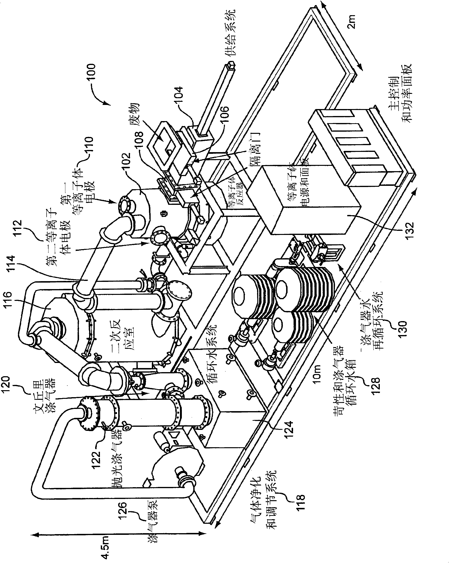
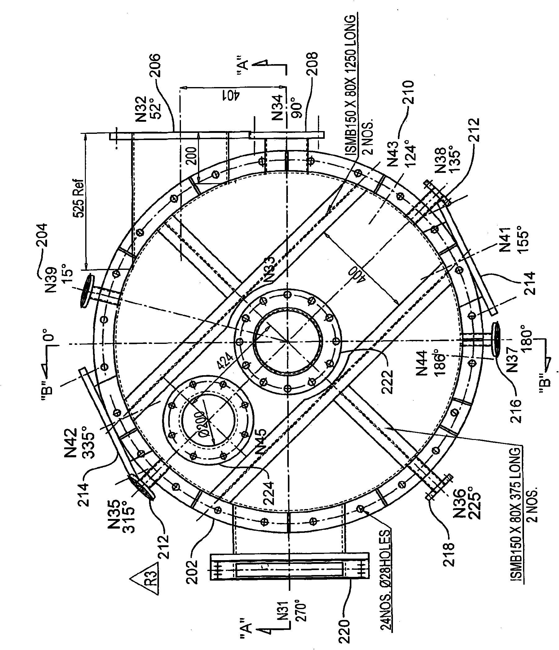
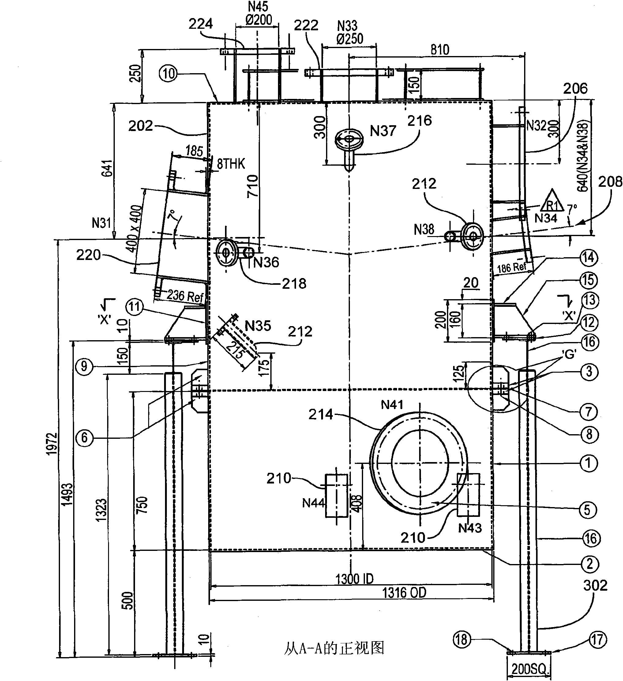
[0050] By applying energy, waste treatment systems process waste. The system can receive and process inorganic and / or organic solid waste, semi-solid waste and / or liquid waste. The system can include a plasma torch having a plurality of electrodes whose positions can be varied to facilitate processing of received waste.

[0051] figure 1is a block diagram of the waste treatment system 100 . The waste treatment system 100 can treat inorganic and / or organic solid waste, semi-solid waste and / or liquid waste. The waste treatment system 100 may be controlled by a computerized control system located near the waste treatment system 100 or at a distance from the waste treatment system 100 . The computerized control system may include one or more processors, memory for accessing or executing software applications (eg, random access memory, read only memory, flash memory, and / or other optical or digital storage devices), and network connection ports. The computerized control system ...


PUM


Abstract

A waste treatment system processes waste upon the application of energy. The system includes a vessel that has an open space that receives waste feedstock. At least two plasma electrodes are mounted to the vessel. An electrode movement control system may position the plasma electrodes to facilitate a pryolysis process to treat the waste feedstock.

Description

[0001] This application claims the benefit of US Provisional Application No. 61 / 027117, filed February 8, 2008, which is incorporated by reference. technical field [0002] The present invention relates to the treatment of waste materials, and more particularly to the controlled thermal decomposition of hazardous and non-hazardous substances. Background technique [0003] The present invention relates to the treatment of waste materials and in particular to the controlled thermal decomposition and conversion of hazardous and non-hazardous substances into usable products. [0004] Waste may be in solid, semi-solid or liquid form and may include organic and / or inorganic materials. Some solid waste is disposed of in landfills. However, public opposition and regulatory pressure may limit the implementation of some landfills. [0005] Other solid and some liquid wastes are disposed of through combustion and / or incineration. These processes generate large amounts of fly ash (to...

Claims


Application Information

Patent Timeline
IPC IPC(8): A62D3/19
CPCC10J3/20F23G5/085C10J3/18F23J2219/40C02F2103/343C10J2300/1634C10J2200/12C10J2300/1238C02F2209/02C02F2103/365C02F2101/306F23G5/027C10J2200/156F23G5/16C02F1/4608F23G2204/201H05K999/99C02F2201/4612F23G2201/303C10K3/003C10J3/723C10K1/101C02F2101/363F23G2201/40C02F2301/08C10K1/122C10J2200/154C10K1/003C10J3/30
Inventor 乔斯·A·卡波特迪帕克·沙阿帕拉梅斯瓦兰·韦努戈帕尔吴宪丹尼尔·里佩斯约瑟夫·A·罗辛
Owner PEAT INT INC
Learn More