Large-carrying capacity off-highway dump truck
A non-highway and dump truck technology, which is applied in the direction of inclined load-carrying vehicles, etc., can solve the problems of inconvenient processing, poor economic performance, and high noise, and achieves favorable assembly and welding, good driving comfort, and strong carrying capacity Effect
- Summary
- Abstract
- Description
- Claims
- Application Information
AI Technical Summary
Problems solved by technology
Method used
Image
Examples
Embodiment 1
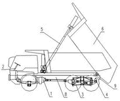
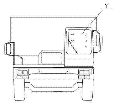
[0073] Example 1 as figure 1 and figure 2 As shown, this non-highway dump truck with a large load capacity includes a car body, a vehicle frame, a power system, a transmission system, a carriage, tires, and a braking system. Its power system 1 is connected to the main frame 8, The steering system 2 is connected to the left front outside of the main frame 8, the suspension system 3 is connected below the main frame 8, the braking system 4 is connected to the inside and outside of the main frame 8, and the hydraulic cylinder of the lifting system 5 passes through the cylinder. The connection seat is connected on the front end of the subframe 9 and the front plate of the cargo box 6, the cargo box 6 is connected on the subframe 9, the subframe 9 is connected on the main frame 8 through a bracket and a connecting plate, and the cab 7 It is connected to the left front of the main frame through a bracket.
[0074] It is aimed at the special working conditions of the construction ...
Embodiment 2
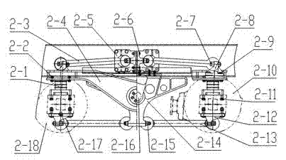
[0088] Embodiment 2 is basically the same as Embodiment 1, and the difference is that its suspension is a balance beam suspension such as Figure 2-1As shown, there are four rubber main springs 2-1 in total, two of which are connected to the two ends of the equalizing beam 2-4 on the left side of the vehicle frame 2-23 by bolts 2-2, and the other two are connected by bolts 2-2 to the The two ends of the equalizing beam 2-4 on the right side of the vehicle frame 2-23, and the bottom of the four rubber main springs 2-1 are respectively connected to the axle housing processing surfaces of the middle axle 2-18 and the rear axle 2-10 through bolts 2-11 The middle part of the balance beam 2-4 is connected to the two ends of the balance shaft 2-16 with rubber bearing 2-19, rubber bearing cover 2-20, and bolt 2-21, and the balance shaft 2-16 is fixed on the balance shaft support 2-14 Among them, the two balance shaft brackets 2-14 are respectively connected to the vehicle frame 2-23 t...
Embodiment 3
[0089] Embodiment 3 is basically the same as Embodiment 1, and the difference is that its suspension is another kind of suspension structure such as Figure 3-1 As shown, it is the longitudinal distribution diagram of embodiment 3, the upper thrust rod 3-1 and the lower thrust rod 3-13, the middle bridge 3-14 and the support 3-11, and the four balance beams 3-15 pass through the upper thrust rod beam end The connection of support 3-2, upper thrust rod bridge end support 3-4 and lower thrust rod support 3-9 forms two side-by-side four-bar linkages at the front end and rear end of four balance beams 3-15, which can effectively control Longitudinal runout of middle axle 3-14 and rear axle 3-16. The two ends of the four upper thrust rods 3-1 are respectively connected to the upper thrust rod beam end support 3-2 and the upper thrust rod bridge end support 3-4 by two bolts 3-17, and the upper thrust rod beam end support 3-2 is single The limit is connected on four beams 3-15 and t...
PUM
 Abstract
Description
Claims
Application Information
 - R&D
- Intellectual Property
- Life Sciences
- Materials
- Tech Scout
- Unparalleled Data Quality
- Higher Quality Content
- 60% Fewer Hallucinations
Browse by: Latest US Patents, China's latest patents, Technical Efficacy Thesaurus, Application Domain, Technology Topic, Popular Technical Reports.
© 2025 PatSnap. All rights reserved.Legal|Privacy policy|Modern Slavery Act Transparency Statement|Sitemap|About US| Contact US: help@patsnap.com


