Construction method for protecting slope of soil-nail wall and special equipment for protecting slope of soil-nail wall

A construction method and technology of special equipment, applied in excavation, sheet pile walls, foundation structure engineering, etc., can solve the problems of equipment not working, low production efficiency, high labor intensity, etc., and achieve improved work efficiency, low site requirements, good adaptability

Inactive Publication Date: 2011-03-09
沈全斌
View PDF5 Cites 3 Cited by
  • Summary
  • Abstract
  • Description
  • Claims
  • Application Information

AI Technical Summary

Problems solved by technology

However, the existing soil nail wall anchor construction machinery basically adopts the construction method combining manual and mechanical from the hole forming anchor to the driving anchor, and its disadvantages are obvious: labor intensity is large, and two Different Construction Machines: Electric Drilling Machines and Pneumatic Driving Hammers
More importantly, these special hole-forming equipment need a relatively spacious or ideal working surface, and the transportation and walking of these special equipment require ideal roads, which are precisely what the construction site is difficult to provide
Sometimes there is a conflict with the working surface of the excavator, which causes the equipment to fail to work when the excavator is working, which affects the work efficiency of the entire project
At the same time, the pneumatic bolter also has many disadvantages such as difficulty in driving in, high labor intensity, low production efficiency, and hidden dangers of unsafe construction personnel.

Method used


Image

  • Construction method for protecting slope of soil-nail wall and special equipment for protecting slope of soil-nail wall
  • Construction method for protecting slope of soil-nail wall and special equipment for protecting slope of soil-nail wall
  • Construction method for protecting slope of soil-nail wall and special equipment for protecting slope of soil-nail wall

Examples


Embodiment Construction

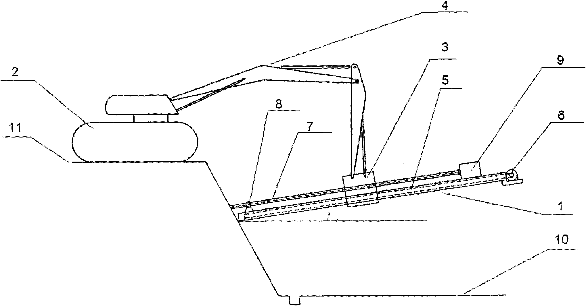
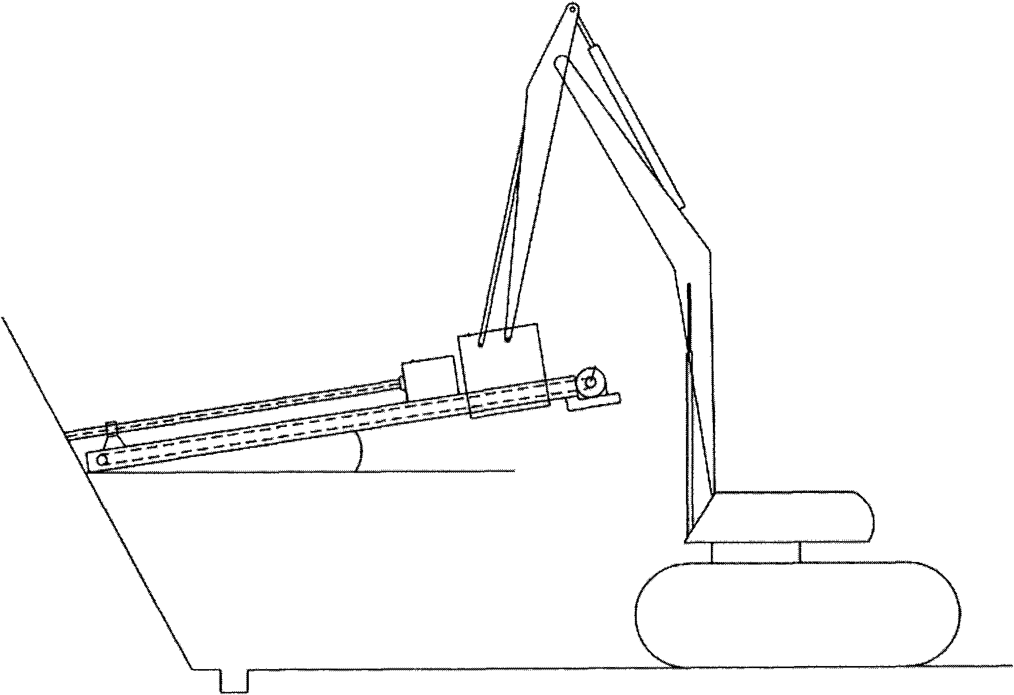
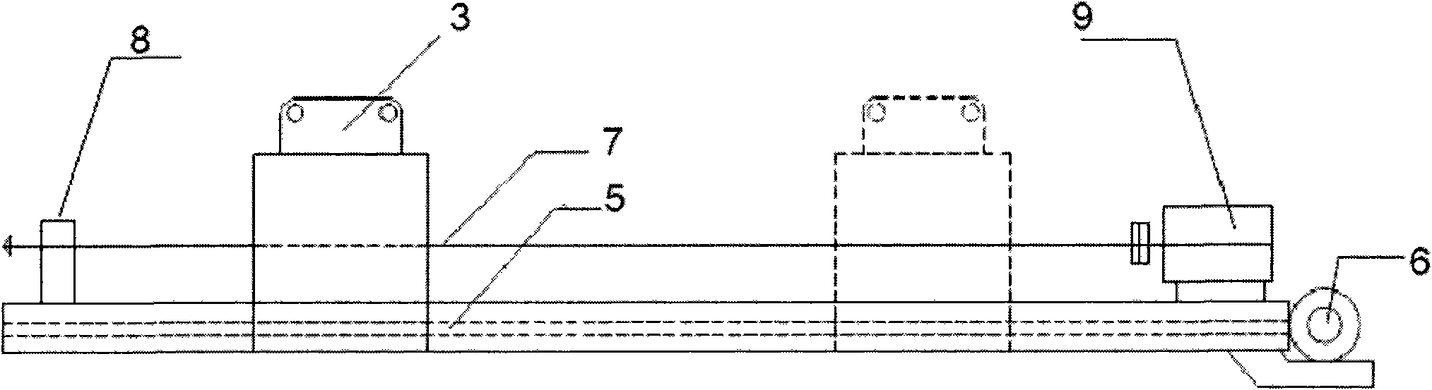
[0023] The present invention will be further described in detail below in conjunction with the drawings and specific embodiments. As shown in the figure, it includes: bolter 1, excavator type platform 2, connecting support 3, movable arm 4, frame 5, transmission motor 6, drill rod or anchor rod 7, positioning frame 8, power unit 9, base Pit 10, upward bevel 11.

[0024] This construction method is to drill, drive into the bolter 1 and connect the excavator or excavator type platform 2 through the connecting support 3, and the machine can operate as long as the excavating machine can pass through. When there is no operating scene in the lower part of the foundation pit at the construction site, the equipment can be parked on the upward slope 11 by adjusting the movable arm 4 of the excavator, and the construction can be performed from top to bottom; otherwise, the excavator can also be parked in the foundation pit 10, from below Construction upwards. The positioning frame 8 fixe...


PUM


Abstract

The invention discloses a construction method for protecting a slope of a soil-nail wall and special equipment for protecting the slope of the soil-nail wall. After the method and the special equipment of the invention are adopted, the equipment can be operated in the position at which a soil excavating machinery can pass through because a drill hole and a blow-in bolter is linked with an excavator or an excavator type platform. The equipment has low requirements on the site and can finish the slop protection working under extremely serious working conditions. When the lower part in a base pit of the construction site has no working scene, the equipment can be stopped at the upper slope opening and constructs downwards by adjusting large and small arms of the excavator, and the excavator can construct in the base pit from bottom to top vice versa. When a vertical anchor rod is required for construction, the equipment has no any difficulty and extremely high efficiency. The construction working method and the special equipment of the invention can solve the difficulty of working surface competition with the excavator machinery, the base pit working surface exposed due to soil excavation can be reinforced and processed in the shortest time, and the working efficiency can be greatly enhanced.

Description

Technical field [0001] The invention relates to a slope protection construction method and related equipment, in particular to a soil nail wall slope protection construction operation method. Background technique [0002] The bolter is also called an anchor drill in some places, and it is a drilling tool for bolt support in coal mine roadways. It has outstanding advantages in improving the supporting effect, reducing supporting costs, accelerating the speed of roadway formation, reducing auxiliary transportation, reducing labor intensity, and increasing the utilization rate of roadway section. The bolting rig is the key equipment for bolt support. It affects the quality of bolt support-the orientation, depth, and hole diameter accuracy of the bolt hole, and the quality of bolt installation, as well as the personal safety and labor of the operator. Strength and working conditions, etc. According to the structure, it is divided into single type and drill carriage type; according ...

Claims


Application Information

Patent Timeline
IPC IPC(8): E02D17/20E02D17/04E02D5/74E02D7/18
Inventor 沈全斌
Owner 沈全斌
Why Eureka
Try Eureka