System and method for detecting optical fiber faults of passive optical network

An optical fiber fault detection, passive optical network technology, applied in the field of communication, can solve the problems of OTDR unable to distinguish signals, signal submergence, unable to receive branch optical fibers, etc., to avoid signal overlap and ensure the effect of detection ability and accuracy

Active Publication Date: 2011-03-09
ZTE CORP
View PDF4 Cites 40 Cited by
  • Summary
  • Abstract
  • Description
  • Claims
  • Application Information

AI Technical Summary

Problems solved by technology

[0006] 1. If the distance from part of the branch fiber to the optical splitter is approximately equal, the OTDR cannot tell which branch fiber signal it is, unless a high-resolution OTDR is used
but the highest resolution available now is 2 meters
[0007] 2. If the splitting ratio of the optical splitter is very large, the Rayleigh reflection signal of the branch fiber will have a large loss when passing through the optical splitter. When it reaches the detector of the OTDR, the signal has been submerged in the noise
What's worse is that for ODN with a large splitting ratio (such as: above 1:128 splitting ratio), the gain brought by the filter may not be enough for the loss of the splitter, so the OTDR equipment at the local office may not be able to receive to any information from the branch fiber

Method used


Image

  • System and method for detecting optical fiber faults of passive optical network
  • System and method for detecting optical fiber faults of passive optical network
  • System and method for detecting optical fiber faults of passive optical network

Examples


Embodiment Construction

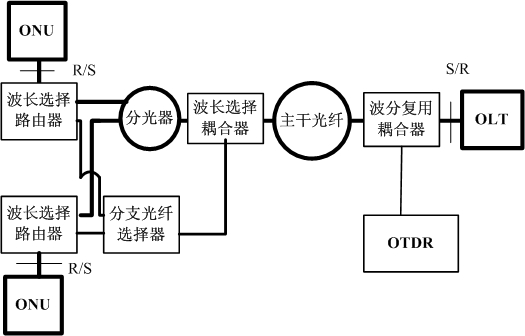
[0058] see image 3 , the system for detecting fiber faults in passive optical networks in the embodiment of the present invention includes: OTDR equipment that can send monitoring instructions, a wavelength division multiplexing coupler, a wavelength selective coupler, a branch fiber selector, and more than one wavelength connected to the splitter Select a router. Among them, the wavelength division multiplexing coupler is connected with the OTDR equipment and the optical line terminal OLT, and is connected with the wavelength selection coupler through the trunk fiber; the wavelength selection coupler is connected with the optical splitter and the branch fiber selector; the branch fiber selector is connected with each wavelength Select routers to connect; each wavelength select router is respectively connected to the optical network unit through the corresponding branch optical fiber. An optical splitter is connected to each wavelength selective router.

[0059] An OTDR dev...


PUM


Abstract

The invention provides a system and a method for detecting optical fiber faults of a passive optical network. The method comprises the following steps: optical time domain reflectometry (OTDR) equipment gives a command aiming at the detection of a certain branch of optical fiber; a branch optical fiber selector communicates the optical path of the branch optical fiber specified by the command after receiving the command; the OTDR equipment analyzes whether an emitting signal is abnormal or not to confirm whether the backbone optical fiber or the corresponding branch optical fiber has faults or not according to a reflected signal corresponding to the received optical distance detection signal after the optical distance detection signal is emitted; in the invention, the trunk and all the branches of optical fiber in the passive optical network can be monitored, detected and positioned, and the branch optical fiber corresponding to an OTDR monitoring signal is selected to detect by selecting the OTDR monitoring signal so that the problems of signal overlap and difficult division of the branch optical fibers with the same length can be avoided.

Description

technical field [0001] The invention relates to an optical network system in the field of communication, in particular to a system and a method for detecting a failure of an optical fiber in a passive optical network. Background technique [0002] The rapid development of network technology and the popularization of network applications, such as network communication, network shopping, and network entertainment, have become part of modern people's life, so the existing access network copper wire (wired) system is far from meeting this requirement. A high-speed and broadband demand, and the passive optical network is broadband and high-speed, environmental protection and energy-saving broadband access technology, is the best candidate to replace the existing access network, it is being accepted by most operators And be deployed to meet the growing communication users and faster and better service needs. [0003] Passive Optical Network (PON) is a point-to-multipoint optical ...

Claims


Application Information

Patent Timeline
Patent Type & Authority Applications(China)
IPC IPC(8): H04B10/08H04J14/02H04Q11/00H04B10/071
CPCH04B10/071
Inventor 徐继东
Owner ZTE CORP
Why Eureka
Try Eureka