Fiber reinforced plastic-concrete composite beam
A technology of fiber-reinforced plastics and reinforced plastics, applied in bridges, joists, girders, etc., can solve the problems of large initial investment, low stiffness, and low strength utilization rate, and achieve the effects of anti-fatigue, low price, and light weight
- Summary
- Abstract
- Description
- Claims
- Application Information
AI Technical Summary
Problems solved by technology
Method used
Image
Examples
Embodiment 1
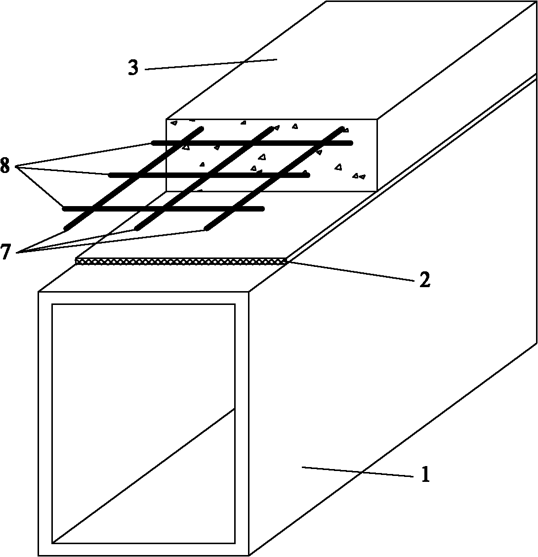
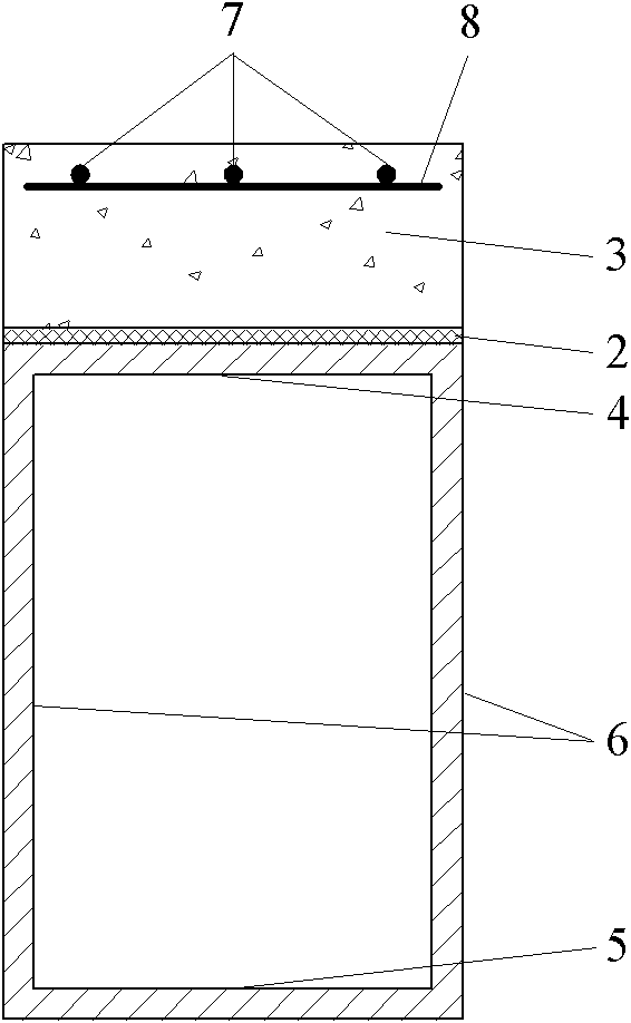
[0025] Such as figure 2 and Figure 6 Shown, the composite beam that the present invention provides is the FRP-concrete composite beam that adopts box-shaped FRP beam and shear connector to be fine stones, mainly by box-shaped FRP beam 1, shear connector (fine stone) 2 and FRP reinforced concrete Plate 3 composition. (1) Box-shaped FRP beam 1 is composed of upper flange 4, lower flange 5 and double-row web 6, the upper end of web 6 is connected to upper flange 4, the lower end is connected to lower flange 5, web 6 and upper flange 4 is perpendicular to the lower flange 5; continuous fiber felt or cloth and continuous fiber bundles are formed by pultrusion process, and the fiber used is one of glass fiber, carbon fiber, basalt fiber, aramid fiber or a mixture of these four fibers. (2) The shear connector (fine stone) 2 adopts the bonded fine stone method: first, use coarse sandpaper or a grinder to polish the upper surface of the FRP beam upper flange 4; secondly, use aceton...
Embodiment 2
[0027] Such as figure 2 and Figure 6 Shown, this composite beam of the present invention is the FRP-concrete composite beam that adopts box-shaped FRP beam and shear connector as adhesive, mainly consists of box-shaped FRP beam 1, shear connector (adhesive) 2 and FRP reinforced concrete slab 3 composition.
[0028] Wherein the specific manufacturing method of the box-shaped FRP beam 1 and the FRP-reinforced concrete slab 3 is the same as that of Embodiment 1. The shear connector (adhesive) 2 uses the adhesive to directly bond the concrete: first, use coarse sandpaper or a grinder to polish the upper surface of the FRP beam upper flange 4; second, use acetone to scrub the polished surface; finally, use acetone to scrub the polished surface Evenly brush a layer of 2-3mm thick epoxy adhesive suitable for curing in a humid environment. The concrete needs to be poured before the epoxy adhesive is cured, and then cured together.
Embodiment 3
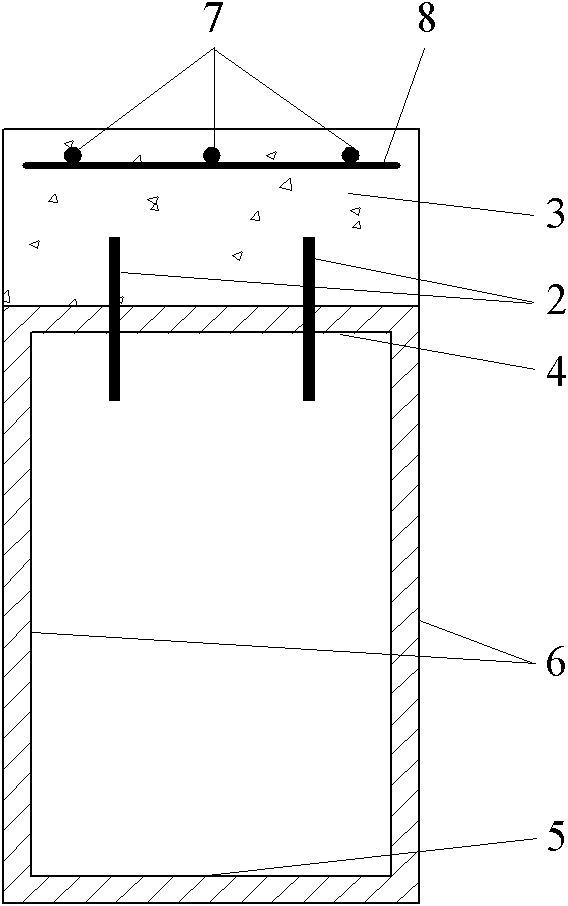
[0030] Such as image 3 and Figure 7 Shown, this composite beam of the present invention is the FRP-concrete composite beam that adopts box-shaped FRP beam and shear connector to be FRP shear nail, mainly by box-shaped FRP beam 1, shear connector (FRP shear nail) 2 It is composed of 3 FRP reinforced concrete slabs.
[0031] Wherein the specific manufacturing method of the box-shaped FRP beam 1 and the FRP-reinforced concrete slab 3 is the same as that of Embodiment 1. The shear connector (FRP shear stud) 2 adopts the method of embedding FRP shear studs, and the FRP shear studs use deformed FRP tendons: firstly, use a drilling machine to open a round hole on the upper flange 4 of the FRP beam, and the diameter of the round hole is slightly smaller than The diameter of the FRP shear nail (interference fit), the vertical and horizontal distance between the round holes, the distance between the round holes at the longitudinal ends and the longitudinal ends, and the distance bet...
PUM
| Property | Measurement | Unit |
|---|---|---|
| particle diameter | aaaaa | aaaaa |
Abstract
Description
Claims
Application Information
 - R&D
- Intellectual Property
- Life Sciences
- Materials
- Tech Scout
- Unparalleled Data Quality
- Higher Quality Content
- 60% Fewer Hallucinations
Browse by: Latest US Patents, China's latest patents, Technical Efficacy Thesaurus, Application Domain, Technology Topic, Popular Technical Reports.
© 2025 PatSnap. All rights reserved.Legal|Privacy policy|Modern Slavery Act Transparency Statement|Sitemap|About US| Contact US: help@patsnap.com


