

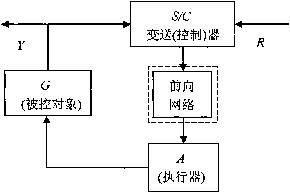
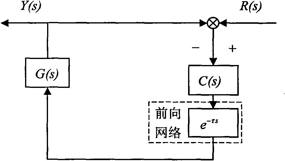
Network delay compensation method between transducer (controller) node and actuator node
A network delay and compensation method technology, applied in the direction of comprehensive factory control, electrical program control, comprehensive factory control, etc., can solve the problems of system loss of stability, reduce the impact of delay system stability, and complete synchronization of difficult node clocks. Achieve the effect of avoiding inaccurate delay estimation model, enhancing robustness and anti-interference ability, and exempting node clock signal synchronization
- Summary
- Abstract
- Description
- Claims
- Application Information
AI Technical Summary
Problems solved by technology
Method used
Image

Examples
Embodiment Construction
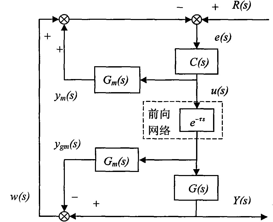
[0066] The following will refer to the attached image 3 Exemplary embodiments of the present invention are described in detail to make the above and other features and advantages of the present invention more apparent to those skilled in the art.
[0067] The specific implementation steps are as follows:
[0068] The first step: the transmitter (controller) node working in the time-driven mode outputs the output signal Y(s) of the controlled pair G(s) and the estimated modulus G of the controlled object m (s) output signal y gm (s) is periodically sampled, and Y(s) and y gm (s) Implement subtraction to obtain the model deviation signal w(s); combine the given signal R(s) with w(s) and y m (s) implement the subtraction operation to obtain the error signal e(s); implement the control algorithm C(s) on e(s) to obtain the control signal u(s); pass the control signal u(s) through the forward network path Transmission to the executor node;
[0069] Step 2: The executor node wo...
PUM
 Abstract
Description
Claims
Application Information