Device for maintaining stability of polarization direction and energy of optical signals with low repetition frequency and short pulse
A technology of repetition frequency and polarization direction, applied in lasers, laser parts, electrical components, etc., can solve the problems of difficulty in real-time compensation of optical pulse signals, difficulty in energy collection, and low repetition frequency, and achieves simple structure and easy system integration. , the effect of reducing the measurement error
- Summary
- Abstract
- Description
- Claims
- Application Information
AI Technical Summary
Problems solved by technology
Method used
Image

Examples
Embodiment Construction
[0024] The present invention will be further described below in conjunction with the embodiments and accompanying drawings, but the protection scope of the present invention should not be limited thereby.
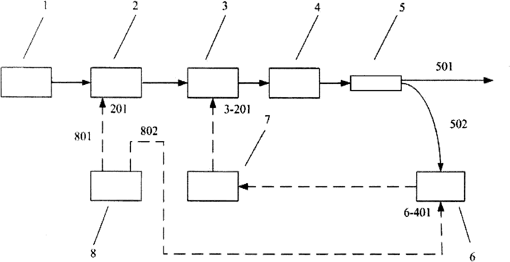
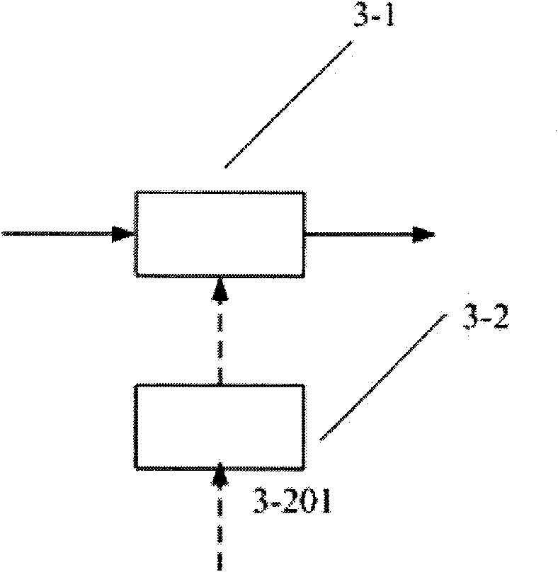
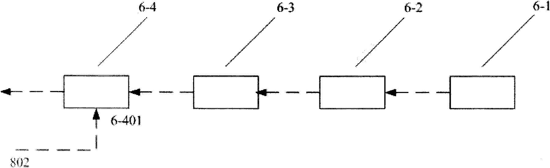
[0025] see first figure 1 , figure 2 with image 3 , figure 1 It is a structural schematic diagram of the device for maintaining the polarization direction and energy stability of low repetition frequency short pulse optical signals according to the present invention, figure 2 is a structural schematic diagram of the feedback unit of the present invention, image 3 It is a structural schematic diagram of the control unit of the present invention. It can be seen from the figure that the device for maintaining the polarization direction and energy stability of low repetition frequency short pulse optical signals in the present invention consists of a continuous fiber laser 1, an optical pulse generator 2, a polarization control unit 3, a polarizer 4, a fiber beam splitter...
PUM
| Property | Measurement | Unit |
|---|---|---|
| Pulse width | aaaaa | aaaaa |
Abstract
Description
Claims
Application Information