Plasma generating device

A technology for generating device and plasma, applied in the direction of plasma, etc., can solve the problem of uneven distribution of plasma, and achieve the effect of reducing energy consumption rate, long distribution distance, and high energy utilization rate

Inactive Publication Date: 2011-03-23
DELTA ELECTRONICS INC
View PDF1 Cites 4 Cited by
  • Summary
  • Abstract
  • Description
  • Claims
  • Application Information

AI Technical Summary

Problems solved by technology

However, the design of dual electromagnetic wave sources requires good and precise control to generate a stable and uniform plasma. At the same time, a specific power operating point must be found, otherwise it is easy to cause uneven plasma distribution

Method used


Image

  • Plasma generating device
  • Plasma generating device
  • Plasma generating device

Examples


Embodiment Construction

[0032] Relevant technical content and detailed description of the present invention, cooperate accompanying drawing to illustrate as follows:

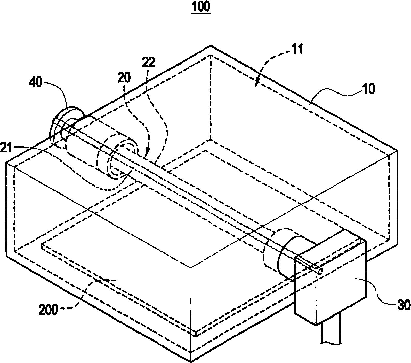
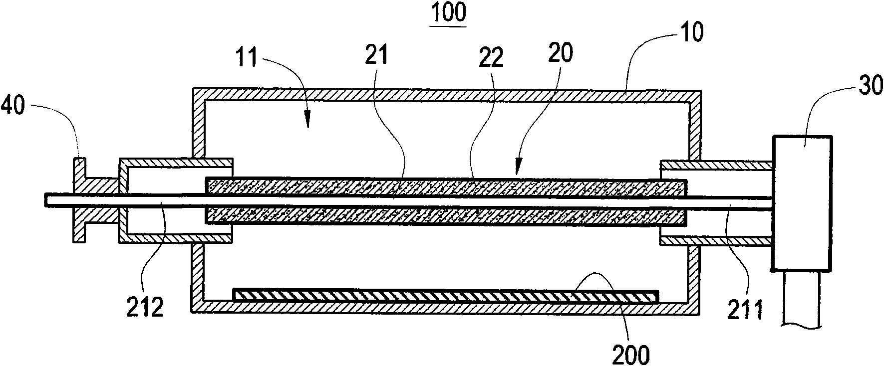
[0033] refer to figure 1 and figure 2 , is the first preferred embodiment of the plasma generating device 100 of the present invention. The plasma generating device 100 is used for plasma thin film deposition or plasma etching treatment on a substrate 200 . The plasma generating device 100 mainly includes a hollow cavity 10 , a slow wave antenna 20 , and an electromagnetic wave generator 30 .

[0034] The hollow cavity 10 is roughly a hollow cuboid, which can be made of metal, but not limited thereto. The hollow cavity 10 has an accommodating space 11 therein. The accommodating space 11 can accommodate the substrate 200 therein.

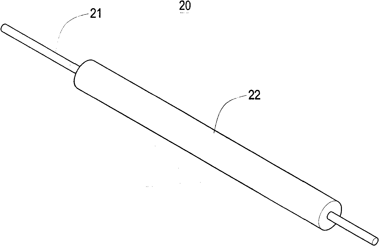
[0035] The slow wave antenna 20 is roughly located in the accommodation space 11 . The slow-wave antenna 20 has a central conductive tube 21 transversely extending through the entire accommodating space...


PUM


Abstract

The invention provides a plasma generating device, comprising a hollow cavity, a slow wave antenna, and an electromagnetic wave generator. The hollow cavity is provided with an accommodating room. The slow wave antenna is provided with a center conducting pipe penetrating through the accommodating room, and a set of dielectric tubes arranged on the center conducting pipe. The electromagnetic wave generator is coupled with the electromagnetic wave on the slow wave antenna, thus the electromagnetic wave generator transmits and radiates the electromagnetic wave to the accommodating room through the slow wave antenna to generate the plasma with uniform intensity.

Description

technical field [0001] The present invention relates to a plasma generating device, in particular to a plasma generating device for thin film process or etching process. Background technique [0002] Plasma enhanced chemical vapor deposition (PECVD) is a common coating technique for growing thin films. Generally speaking, plasma-assisted chemical vapor deposition systems are classified according to the type of plasma excitation source, including radio frequency plasma and microwave plasma. RF plasma mainly includes capacitively coupled plasma (CCP) and inductively coupled plasma (ICP). Microwave plasma has been paid more and more attention due to its high plasma density, high electron ionization rate, no need for electrodes, and relatively simple system structure. [0003] In order to obtain a large-area coating area, the microwave plasma generating device can be designed as a line type, which penetrates a conductive antenna in a vacuum chamber, and sets a columnar quartz ...

Claims


Application Information

Patent Timeline
Patent Type & Authority Applications(China)
IPC IPC(8): H05H1/46
Inventor 寇崇善潘彦儒林欣桦王腾纬詹议翔林瑞堉
Owner DELTA ELECTRONICS INC
Why Eureka
Try Eureka