
Novel absorption tower

An adsorption tower and a new type of technology, applied in the field of adsorption towers, can solve the problems of low gas flow rate, increased adsorbent loading, easy pulverization, etc., and achieve the effect of uniform flow rate in the outlet section and improved utilization rate.

Inactive Publication Date: 2011-03-30
张文波
View PDF0 Cites 6 Cited by
  • Summary
  • Abstract
  • Description
  • Claims
  • Application Information

AI Technical Summary

Problems solved by technology

However, after a long period of equipment operation in the adsorption tower, the carbon molecular sieve bed will more or less wear and sink.
Using this method of hard pressing to fix the bed, because the coconut mat has a certain degree of elasticity, although the carbon molecular sieve bed can be guaranteed not to loosen in a short period of time, after a year or more of operation, when the carbon molecular sieve When the bed sinks beyond the elastic expansion height of the coconut mat, the bed will loosen, and the carbon molecular sieve bed will become easy to pulverize, resulting in a decrease in the purity of the adsorption tower
[0003] Moreover, the holes on the gas flow distribution plate at the bottom of the adsorption tower in the prior art usually adopt a uniform distribution hole pattern, but the gas flow distribution near the center of the circle is easy to cause the gas flow velocity at the center of the circle to be large, and the gas flow velocity at the place far away from the center of the circle is small.
Therefore, when the mixed gas enters from the air inlet of the adsorption tower, the gas distribution is uneven, so that the effective utilization rate of the adsorbent packing is very low. In the prior art, in order to ensure the adsorption effect of the adsorption tower, the loading capacity of the adsorbent has to be increased.

Method used


Image

  • Novel absorption tower
  • Novel absorption tower
  • Novel absorption tower

Examples


Embodiment Construction

[0021] Preferred embodiments of the present invention will be described in detail below in conjunction with accompanying drawing:

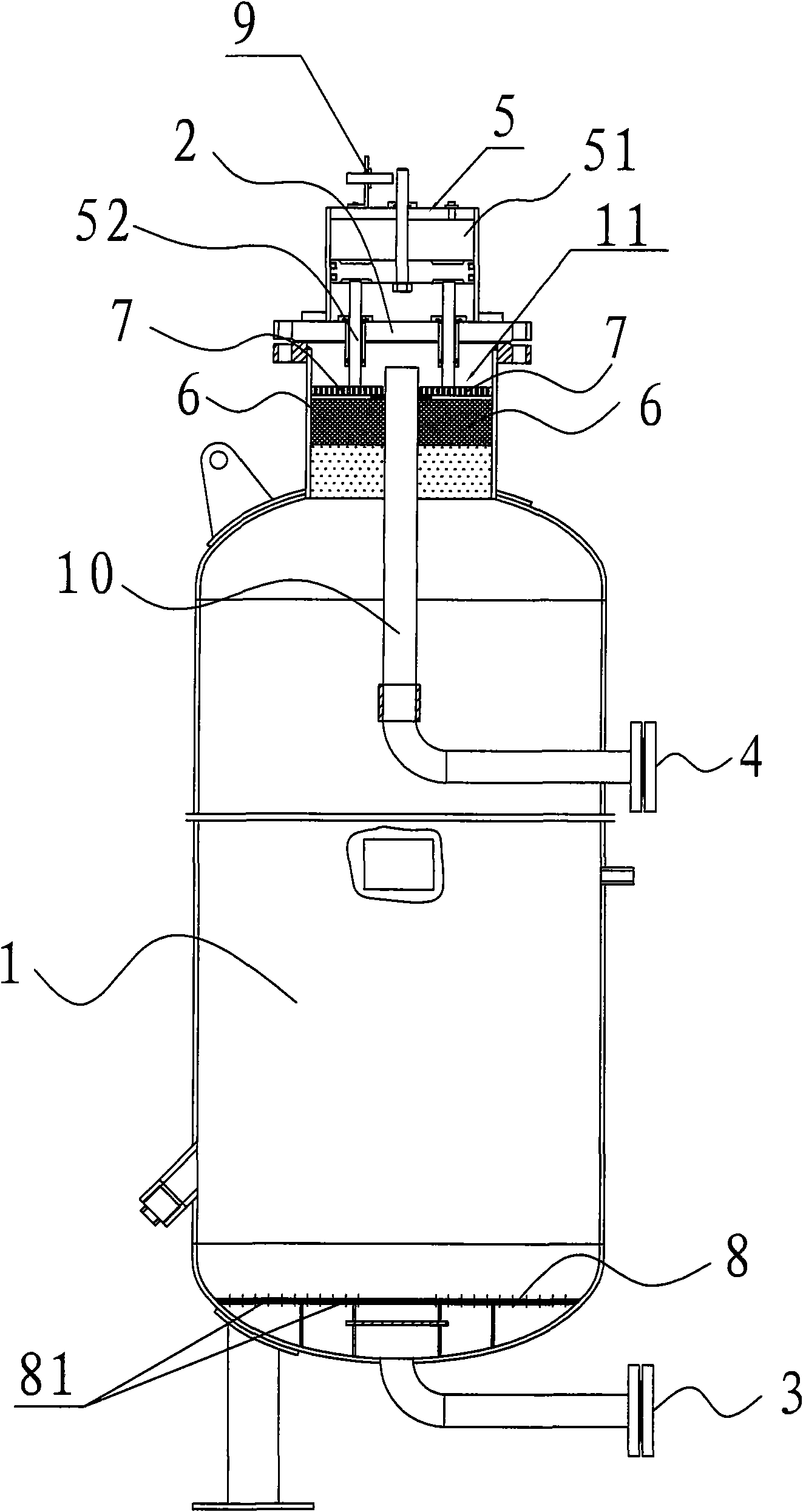
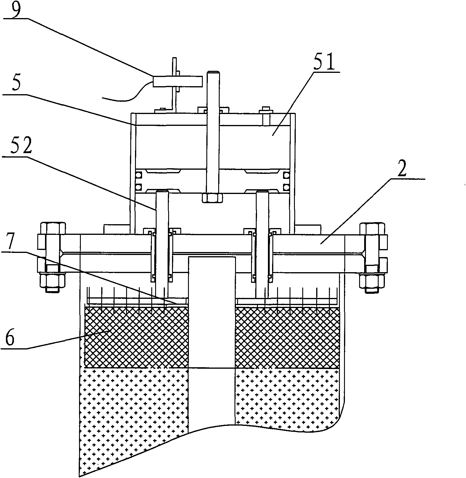
[0022] as attached figure 1 And attached figure 2 As shown, a new type of adsorption tower, which includes a tower body 1 for placing an adsorbent bed, a sealing cover 2 arranged on the top of the tower body 1, and an air inlet opened on the tower body 1 3 and air outlet 4. The sealing cover 2 is provided with a cylinder pressing device 5 for pressing down the adsorbent bed. The mixed gas after compression, oil removal and water removal enters from the air inlet 3 at the bottom of the tower body 1, and after passing through the gas flow distribution plate 8 and the carbon molecular sieve bed, the mixed gas such as nitrogen and impurity gases such as oxygen in a certain pressure state After being adsorbed into the micropores of the carbon molecular sieve, the nitrogen gas directly passes through the carbon molecular sieve bed and is sent to the...


PUM


Abstract

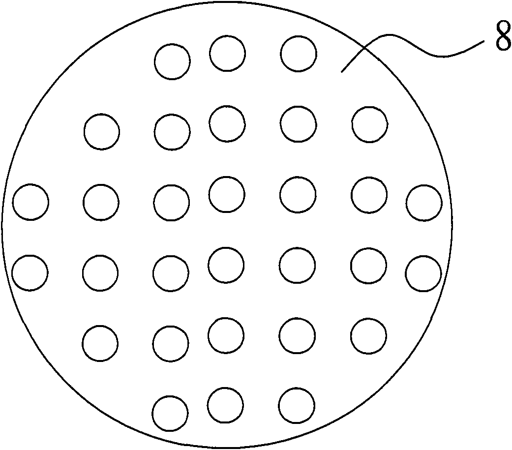
The invention relates to a novel absorption tower which comprises a tower body, a sealing cover, an air inlet and an air outlet, wherein the tower body is used for placing an absorbing agent bed layer, the sealing cover is arranged at the top of the tower body, the air inlet and the air outlet are arranged on the tower body, an air cylinder compression device used for downwards compressing the absorbing agent bed layer is arranged on the sealing cover, an air flow distribution plate is arranged above the air inlet inside the tower body, a plurality of holes are arranged on the air flow distribution plate, and the hole diameters of the holes are gradually increased from the circle center of the air flow distribution plate in the radial direction. When a carbon molecular sieve bed layer downwards sinks, a piston rod of the air cylinder compression device pushes the hole plate and a cocoa pad to downwards move for tightly compressing the carbon molecular sieve bed layer, and the carbon molecular sieve bed layer is ensured not to get loose, so the pulverization phenomenon of the molecular sieve bed layer can be prevented. In addition, the hole diameters are gradually increased from the circle center of the air flow distribution plate in the radial direction, so the flow rate at the cross section of an air flow outlet can be uniform, and the utilization rate of the absorbing agent can be greatly improved.

Description

technical field [0001] The invention relates to an adsorption tower used for adsorbing other impurity gases in mixed gas in gas production. Background technique [0002] A traditional adsorption tower usually includes a tower body and a coconut mat arranged in the tower body for compacting the adsorbent bed. When the adsorbent, namely molecular sieve, is placed in the tower body, the molecular sieve bed needs to be compacted to fix the bed to ensure The adsorption purity of the adsorption tower. In the prior art, in order to compact the carbon molecular sieve bed at the mouth of the tower body, hard pressing is mainly used to fix the bed layer by hard pressing the elastic brown layer on it. However, after a long period of equipment operation in the adsorption tower, the carbon molecular sieve bed will be more or less worn and subsidence. Using this method of hard pressing to fix the bed, because the coconut mat has a certain degree of elasticity, although the carbon molecu...

Claims


Application Information

Patent Timeline
Patent Type & Authority Applications(China)
IPC IPC(8): B01D53/04
Inventor 张文波朱亚军王晓东颜庭勇尹泉生
Owner 张文波
Learn More